In triaxial testing, small mistakes don’t stay small. They multiply into wrong strength parameters, misleading stiffness, and unreliable design data.
Most triaxial test errors come from sample preparation, membrane boundary effects, and calibration issues—not from soil variability itself. Controlling these factors is the key to high-quality geotechnical data.
Let’s break it down clearly and practically.
Sample Preparation Errors: The Most Critical Source of Inaccuracy in Triaxial Testing
Sample quality defines the upper limit of test accuracy.
Improper specimen preparation introduces fabric disturbance, density inconsistency, saturation errors, and non-representative soil structure, which directly alters shear strength and deformation behaviour.

Sample preparation is where most triaxial errors begin—even before the test starts. The soil is no longer in its natural state once it is trimmed, compacted, or reconstituted. This means its fabric structure, particle orientation, and void ratio may already be altered.
For cohesive soils, disturbance during sampling (e.g., Shelby tube extrusion) can destroy natural bonding. This leads to:
- reduced apparent cohesion (c),
- softened stress–strain response,
- earlier strain localization.
For granular soils, the biggest issue is density control. Small variations in relative density (Dr) can significantly shift peak friction angle (φ’). Even a ±2–3% density difference can produce noticeable changes in peak strength.
Saturation is another hidden error source. Incomplete saturation leads to low B-values, trapped air, and inaccurate pore pressure response in CU tests. This directly distorts effective stress interpretation.
In real labs, I often see a pattern: engineers assume soil variability is the reason for inconsistent results, when in fact it is specimen inconsistency.
A practical improvement step is strict preparation SOP control:
- consistent trimming tools,
- controlled compaction energy,
- saturation verification (B ≥ 0.95),
- density measurement at multiple points.
For high-precision programs, HOWDY often recommends pairing test design with consistent boundary materials and membranes to eliminate external variability sources like sealing and confinement inconsistency: HOWDY triaxial consistency solutions.
| Preparation Issue | Mechanical Effect | Test Impact |
|---|---|---|
| Density variation | changes interparticle friction | altered peak strength |
| Fabric disturbance | destroys soil structure | lower cohesion |
| Poor saturation | trapped air compressibility | wrong pore pressure response |
Membrane and Boundary Effects That Distort Stress–Strain Results
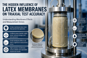
The membrane is not passive—it actively affects measurement.
Latex membrane stiffness, thickness variation, penetration, and wrinkling can modify confining pressure transfer and distort stress–strain and volume change measurements.

In theory, confining pressure (σ₃) is uniformly applied through cell fluid. In reality, the membrane sits between the fluid and the soil, acting as a deformable boundary layer.
Several mechanisms introduce error:
1) Radial restraint effect
A thicker or stiffer membrane increases hoop tension. This adds artificial confinement, making the soil appear slightly stronger and less deformable. The effect is more pronounced in:
- soft clays,
- low confining stress tests,
- high-strain conditions.
2) Membrane penetration
In sands and granular soils, σ₃ forces the membrane into void spaces. This creates an apparent volume reduction that is not real soil compression. It is a boundary artifact.
3) Wrinkling and folding
Oversized membranes create folds that behave like micro-reservoirs. During loading, they expand and contract, producing noisy volume change signals.
4) Leakage and sealing instability
Small defects near O-rings or mounting areas lead to pore pressure drift, especially in CU tests. This affects effective stress path accuracy.
These issues are often mistaken for soil behaviour variability, but in controlled studies they disappear when membrane quality is improved.
This is where membrane engineering matters. HOWDY focuses on high-precision latex membranes with controlled thickness tolerance, stable elasticity, and consistent diameter to reduce boundary uncertainty and improve repeatability in triaxial systems: HOWDY membrane engineering.
| Boundary Issue | Resulting Error | Data Distortion |
|---|---|---|
| Membrane stiffness | higher apparent strength | biased φ’ |
| Penetration | false volume reduction | wrong compressibility |
| Wrinkles | unstable volume curves | poor repeatability |
Instrumentation and Calibration Issues in Triaxial Equipment
Even perfect soil and membranes cannot fix poor measurement systems.
Load cell drift, pore pressure transducer miscalibration, volume change system errors, and axial displacement inaccuracies lead to systematic bias in stress–strain interpretation.

Instrumentation error is often invisible because it is systematic—it shifts all results in the same direction.
1) Load cell calibration error
If axial load is miscalibrated, deviator stress (q = σ₁ − σ₃) is directly wrong. Even small drift can shift peak strength values significantly.
2) Pore pressure transducer offset
A zero error in u measurement leads to incorrect effective stress:
σ’ = σ − u
If u is wrong, everything downstream is wrong.
3) Volume change system inaccuracies
Burette or pressure-volume controller errors affect CD test results. This impacts:
- compressibility curves,
- dilation behaviour,
- permeability interpretation.
4) Axial strain measurement error
Friction, frame compliance, or LVDT misalignment can distort strain readings, especially at small strains (<1%).
In high-quality labs, calibration is not a one-time task—it is a routine validation process before each test series.
Best practice includes:
- zero check before saturation,
- dummy sample validation,
- cross-comparison of sensors.
Best Practices to Improve Triaxial Test Accuracy and Repeatability
Accuracy is not a single fix—it is a system.
High-precision triaxial testing requires controlled sample preparation, high-quality membranes, calibrated instruments, and consistent boundary conditions across all tests.

Improving triaxial accuracy is about eliminating uncertainty sources one by one.
1) Standardize specimen preparation
Consistency in density, saturation, and trimming is the foundation. Without this, no downstream improvement matters.
2) Control membrane quality and boundary effects
Use membranes with:
- tight thickness tolerance,
- consistent elasticity,
- proper diameter matching.
This is where HOWDY membrane solutions are often applied in research and industrial labs. By controlling membrane uniformity and reducing boundary variation, test scatter decreases significantly, especially in CU and CD programs: HOWDY precision membranes.
3) Strict calibration routine
Calibrate load, pressure, and volume systems before every test series. Do not assume stability.
4) Use baseline and repeat tests
Repeatability is the strongest indicator of test quality. If results vary widely, the issue is not soil—it is the system.
5) Integrate system thinking
Soil + membrane + equipment must be treated as one system, not separate parts.
| Improvement Area | Key Action | Result |
|---|---|---|
| Sample prep | standard SOP | reduced scatter |
| Membrane control | thickness + fit control | stable boundary |
| Calibration | routine verification | lower systematic error |
| Repeat testing | validation loop | higher confidence |
Conclusion
Triaxial errors are rarely caused by soil alone. They come from preparation, membranes, and calibration—controlling these is the real path to accurate geotechnical data.