From Lab to Field: Translating Triaxial Test Results into Real-World Engineering Solutions
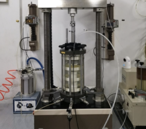
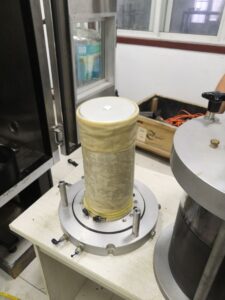
Triaxial tests are a cornerstone of geotechnical investigation, helping engineers understand how soil behaves under stress. But what happens after the lab report is complete? The true value of a triaxial test lies in how effectively its results are applied to real-world engineering problems—from slope stabilization to foundation design. This article explores how engineers bridge the gap between controlled lab data and complex field realities.
Interpreting Soil Parameters for Field Design
Triaxial tests provide fundamental parameters that are direct inputs for design models1:
- Cohesion (c) and Friction Angle (φ) for slope and retaining wall stability
- Young’s Modulus (E)2 for settlement and deformation prediction
- Pore pressure parameters (B and Skempton’s A values) for drainage and loading analysis
These parameters are used to define soil behavior under various conditions—drained or undrained, elastic or plastic—giving engineers the tools to create reliable, load-bearing systems.
Key Soil Parameters from Triaxial Testing
| Parameter | Symbol | Engineering Use |
|---|---|---|
| Shear Strength | c, φ | Stability analysis, retaining structures |
| Modulus of Elasticity | E | Settlement prediction, dynamic analysis |
| Pore Pressure Coefficient | A | Consolidation, slope stability in wet soils |
Without accurate interpretation of these values, designs may be unsafe or overly conservative.
Scaling Laboratory Data to Real-World Conditions
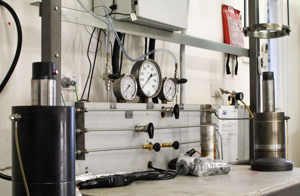
A common challenge in geotechnical engineering is translating small-scale lab data3 into usable information for large, variable, and complex field environments4.
Challenges:
- Sample disturbance during extraction
- Boundary effects and scale differences
- Differences in stress history and environmental loading
To compensate, engineers apply correction factors, back-analysis, and field calibration5. For example, modulus values from stiff clays in the lab are often adjusted downward for in-situ use, while strength parameters may be increased for compacted fill.
Example: Correction Factors for Field Application
| Soil Type | Lab φ (°) | Field φ (°) | Adjustment Rationale |
|---|---|---|---|
| Soft clay | 26 | 23 | Sample disturbance |
| Dense sand | 38 | 36 | Scale effects, stress state |
| Overconsolidated clay | 34 | 31 | Stress relief in sampling |
Such adjustments ensure that designs remain both realistic and conservative.
Integrating Triaxial Results into Numerical Simulations
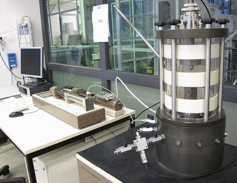
Modern engineering design relies heavily on finite element modeling (FEM)6 and numerical simulations7, where triaxial test results are used to calibrate material models.
Common Constitutive Models:
- Mohr–Coulomb8: Simple and widely used for slope and retaining structures.
- Hardening Soil Model: For more accurate stress-strain behavior in clays and sands.
- Cam-Clay Models: For advanced analysis of normally consolidated clays.
Example: FEM Inputs from Triaxial Testing
| Model Input | Source from Triaxial Test |
|---|---|
| Friction angle (φ) | CD/UU/CIU test results |
| Cohesion (c) | Undrained shear strength (Su) |
| E50 (Secant Modulus) | Stress-strain curve analysis |
| Failure strain | Peak vs. residual strength mapping |
Simulations using well-calibrated models help predict settlement, stability, and deformation under real-world loading with higher confidence.
Validating Designs through Field Monitoring
Lab testing and modeling must ultimately be verified in the field. Engineers use instrumentation and real-time monitoring to compare actual performance against predictions.
Common Monitoring Tools:
- Piezometers for pore pressure measurement
- Inclinometers for slope movement
- Settlement plates and extensometers for vertical deformation
- Strain gauges and pressure cells in deep foundations
When discrepancies arise, models are updated using back-analysis—feeding new field data into the design loop to refine assumptions and improve safety margins.
Field Validation Example
| Parameter | Predicted | Observed | Adjustment Needed |
|---|---|---|---|
| Settlement (mm) | 45 | 60 | Increase E correction factor |
| Slope displacement (mm) | 12 | 8 | No change needed |
| Pore pressure (kPa) | 80 | 100 | Re-evaluate drainage design |
This feedback loop ensures that triaxial test results lead to actionable, verifiable engineering solutions.
Conclusion
Triaxial tests are more than just a lab exercise—they are the starting point for real-world problem-solving. By interpreting soil parameters accurately, scaling them for field conditions, using them in simulations, and validating designs with monitoring, engineers transform laboratory insights into safe, sustainable infrastructure. It’s a journey from specimen to structure—one layer of soil at a time.
-
Understanding direct inputs for design models is crucial for engineers to create effective and reliable systems. ↩
-
Learning about Young’s Modulus is essential for understanding material behavior under stress, vital for engineering design. ↩
-
Understanding small-scale lab data is crucial for effective application in field environments, enhancing your knowledge in geotechnical practices. ↩
-
Exploring this concept helps grasp the challenges faced in real-world applications of geotechnical engineering, enriching your expertise. ↩
-
These techniques are vital for ensuring accurate data translation from lab to field, making them essential for successful engineering projects. ↩
-
Explore this link to understand the fundamentals of FEM and its critical role in modern engineering design. ↩
-
Discover how numerical simulations improve accuracy and efficiency in engineering projects by visiting this resource. ↩
-
Learn about the practical uses of the Mohr–Coulomb model in slope stability and retaining structures by checking this link. ↩

