
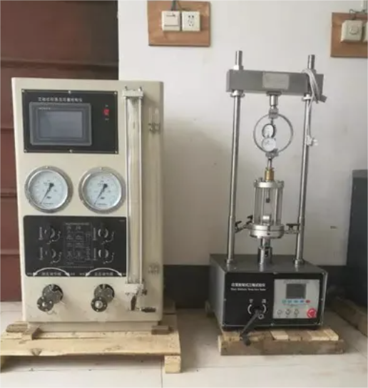
A UU triaxial test apparatus is a laboratory system used to measure the total-stress undrained response of a cylindrical cohesive-soil specimen.
UU means unconsolidated undrained. During the test, drainage is prevented while confining pressure is applied and remains closed during axial shearing. The specimen is not allowed to consolidate under the applied cell pressure before loading.
The apparatus normally includes:
- A triaxial pressure cell
- An axial loading frame
- A cell-pressure control system
- A load-measurement device
- A deformation-measurement device
- A specimen pedestal and top cap
- A flexible latex membrane
- A membrane stretcher
- O-rings or approved end seals
- Data-recording equipment
Compared with a consolidated undrained test, a standard UU setup generally does not require the same saturation, back-pressure, consolidation and pore-pressure-measurement stages. However, the system must still maintain stable cell pressure, correct specimen alignment and reliable membrane sealing.
Important: This article is a practical equipment overview. It does not reproduce or replace ASTM D2850 or another applicable testing standard. Laboratories should obtain the current standard from ASTM International and follow their approved procedures, calibration requirements and quality system.
What Is a UU Triaxial Test?
The UU test is used to evaluate the undrained response of cohesive soil under total-stress conditions.
A prepared cylindrical specimen is enclosed in a flexible membrane and placed inside a pressurized triaxial cell. The selected confining pressure is applied without allowing the specimen to drain. The specimen is then compressed axially while drainage remains closed.
During the shearing stage, the apparatus records axial load and deformation. These measurements are used to calculate the specimen’s stress–strain response and undrained strength under the tested condition.
“Unconsolidated” describes the laboratory procedure: the specimen is not allowed to consolidate under the applied cell pressure before shearing. It does not necessarily mean that the soil in the field has never experienced consolidation.
How Is a UU Test Different From CU and CD Tests?
The principal differences concern consolidation and drainage.
| Feature | UU | CU | CD |
|---|---|---|---|
| Full name | Unconsolidated Undrained | Consolidated Undrained | Consolidated Drained |
| Consolidation before shear | No | Yes | Yes |
| Drainage during shear | No | No | Yes |
| Pore-pressure measurement | Not normally a primary standard output | Yes | Not normally central to drained-strength interpretation |
| Primary interpretation | Total stress | Total and effective stress | Effective stress |
| Relative duration | Usually shortest | Longer | Usually longest |
Main Components of a UU Triaxial Test Apparatus
1. Triaxial Cell
The triaxial cell is a pressure chamber that contains the soil specimen and cell fluid.
Its main functions are to:
- Hold the specimen assembly
- Apply uniform confining pressure
- Allow axial load to be transmitted to the specimen
- Provide a transparent or inspectable chamber
- Maintain pressure without leakage
- Connect to the cell-pressure control system
A typical cell includes:
- Cell base
- Transparent chamber wall
- Cell top
- Loading ram
- Pressure inlet
- Seals
- Pedestal
- Top cap
- Drainage connections
The cell must be rated for the intended pressure range and compatible with the selected specimen dimensions.
[Insert original image: UU triaxial cell with the chamber, loading ram, pedestal, top cap and pressure inlet labeled.]
2. Axial Loading Frame
The loading frame applies vertical compression to the specimen.
A suitable loading frame should:
- Maintain the required deformation rate
- Provide stable axial alignment
- Accommodate the triaxial cell
- Have sufficient load capacity
- Minimize vibration and unintended movement
- Work with the selected load and displacement sensors
Misalignment can introduce bending and nonuniform stress. The triaxial cell, loading ram and specimen should therefore be centered carefully before loading begins.
3. Cell-Pressure Control System
The pressure-control system applies and maintains the confining pressure around the membrane-covered specimen.
It may include:
- Pressure controller
- Regulator
- Pressure transducer or gauge
- Tubing
- Fittings
- Valves
- Cell-fluid reservoir
The pressure range and resolution must be appropriate for the test program.
The system should be checked for leakage before testing. A pressure loss can come from the cell, tubing, fittings, valves or membrane, so the complete pressure path must be inspected.
4. Load-Measuring Device
A load cell, proving ring or other approved force-measurement device records the axial load.
The device must have:
- Suitable capacity
- Adequate resolution
- Current calibration
- Stable mounting
- Correct alignment
A load device that is too large for the expected force may provide inadequate resolution. One with insufficient capacity may be overloaded.
The expected soil strength, specimen area and confining pressure should be considered when selecting the load range.
5. Axial Deformation Measurement
Axial deformation may be measured with:
- LVDT
- Displacement transducer
- Dial gauge
- Another calibrated displacement device
The measurement range must accommodate the expected deformation without reaching the end of travel.
The mounting arrangement should prevent slippage and unintended movement. The initial reading should be checked before loading starts.
6. Pedestal and Top Cap
The specimen is installed between a pedestal and top cap.
These components should:
- Match the specimen diameter
- Support correct axial alignment
- Provide smooth sealing surfaces
- Be clean and free from sharp edges
- Hold the membrane and O-rings securely
Even though drainage is not permitted during standard UU shearing, the apparatus may use drainage connections that must remain closed or be configured according to the applicable procedure.
Sharp edges or damaged sealing surfaces can cut the membrane during installation or pressurization.
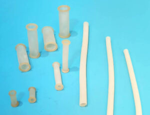
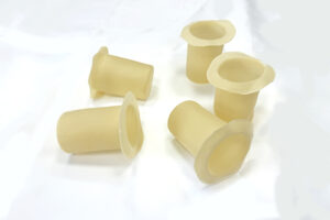
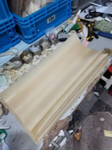
7. Latex Membrane
The latex membrane separates the soil specimen from the triaxial cell fluid.
It must:
- Fit the specimen correctly
- Remain flexible during deformation
- Maintain separation from the cell fluid
- Seal securely at both ends
- Resist installation damage
- Be free from holes, cracks and contamination
An unsuitable or damaged membrane can cause:
- Loss of cell pressure
- Cell fluid entering the specimen
- Incorrect undrained conditions
- Premature test termination
- Unreliable stress–strain results
The membrane should be inspected before every test.
8. Membrane Stretcher
A membrane stretcher expands the flexible membrane so it can be placed over the soil specimen without dragging across its surface.
Depending on its design, the tool may use vacuum to draw the membrane against the inside wall of the stretcher.
A suitable membrane stretcher should:
- Match the specimen and membrane size
- Have smooth internal surfaces
- Produce sufficient expansion
- Release the membrane evenly
- Be clean and free from sharp edges
Incorrect use of the stretcher can cause cuts, uneven stretching or local thinning.
9. O-Rings and End Seals
O-rings secure the membrane around the pedestal and top cap.
The O-rings must:
- Match the component diameter
- Provide sufficient sealing force
- Be free from cracks or cuts
- Sit in the correct position
- Avoid trapping folded membrane material
- Be installed without damaging the membrane
Using more O-rings does not automatically produce a better seal. The arrangement should follow the applicable apparatus and laboratory procedure.
10. Data-Acquisition System
A digital data-acquisition system may record:
- Time
- Axial load
- Axial deformation
- Cell pressure
Some systems calculate axial strain, corrected area and deviator stress during the test.
Automated calculations should still be verified. Incorrect specimen dimensions, sensor ranges, calibration factors or zero readings can produce incorrect results even if the recording software functions normally.
Typical UU Apparatus Layout
| Component | Function | Pre-test check |
|---|---|---|
| Triaxial cell | Contains cell fluid and applies confinement | Inspect seals, chamber and pressure rating |
| Loading frame | Applies controlled axial compression | Check speed and alignment |
| Cell-pressure controller | Applies confining pressure | Check stability and leakage |
| Load cell | Measures axial force | Confirm capacity, zero and calibration |
| LVDT or dial gauge | Measures axial deformation | Confirm range, zero and mounting |
| Pedestal and top cap | Support and align the specimen | Clean and inspect sealing surfaces |
| Latex membrane | Isolates the specimen from cell fluid | Inspect dimensions and condition |
| Membrane stretcher | Assists membrane installation | Check size, vacuum and sharp edges |
| O-rings | Seal the membrane ends | Inspect condition and fit |
| Data-acquisition system | Records test measurements | Verify channels and calibration factors |

Figure 1. Replace this placeholder with an original diagram or photograph of your UU triaxial test apparatus.
Selecting a Latex Membrane for a UU Test
The correct membrane depends on more than the test name.
Important selection factors include:
- Specimen diameter
- Specimen height
- Pedestal and top-cap dimensions
- Required sealing overlap
- Expected axial strain
- Soil surface condition
- Maximum cell pressure
- Membrane material
- Nominal thickness
- Actual dimensional tolerance
Membrane Inside Diameter
The membrane should fit the specimen without excessive looseness or damaging installation strain.
If the membrane is too large, it may form folds or wrinkles. If it is too small, it may be overstretched during installation or become vulnerable to tearing.
Selection should be based on the measured specimen diameter and actual membrane dimensions.
Membrane Length
The membrane must cover the full specimen and provide sufficient material for sealing at the pedestal and top cap.
Required length depends on:
- Specimen height
- End-component geometry
- O-ring positions
- Sealing allowance
- Expected specimen deformation
A membrane that is too short may pull away from an end seal during loading.
Membrane Thickness
Membrane thickness involves a balance between flexibility and durability.
A thinner membrane may reduce unintended restraint but can be more vulnerable to puncture. A thicker membrane may improve handling durability but can exert more mechanical influence on a soft specimen.
The laboratory should select a thickness validated for its specimen, soil condition, pressure range and calculation procedure.
[Insert actual company table: Available inside diameters, lengths, nominal thicknesses and verified manufacturing tolerances.]
Only publish specifications supported by actual production and quality-control records.
Preparing the UU Test Apparatus
Before installing the specimen:
- Confirm that the loading frame is functioning correctly.
- Check the load and displacement devices.
- Verify applicable calibration records.
- Inspect the triaxial cell and seals.
- Check the pressure tubing, valves and fittings.
- Clean the pedestal and top cap.
- Confirm that drainage paths are configured correctly.
- Select a suitable membrane and O-rings.
- Inspect the membrane stretcher.
- Verify the specimen dimensions and identification.
- Prepare the data-acquisition channels.
- Record the initial sensor readings.
A complete pre-test checklist helps prevent losing a prepared specimen because of a simple equipment or sealing problem.
Installing the Specimen and Latex Membrane
Step 1: Inspect the Specimen
Check the specimen for:
- Cracks
- Distortion
- Protruding particles
- Irregular ends
- Surface damage
- Incorrect dimensions
Preparation and trimming must follow the applicable method.
Step 2: Inspect the Membrane
Under adequate lighting, check for:
- Pinholes
- Cuts
- Cracks
- Embedded contamination
- Severe thickness irregularity
- Signs of aging
- Sticky or hardened areas
Reject a visibly damaged membrane.
Step 3: Position the Specimen
Place the specimen centrally on the pedestal without scraping or compressing it unnecessarily.
Check that the specimen axis is aligned with the pedestal and loading system.
Step 4: Load the Membrane Stretcher
Place the membrane inside the clean stretcher and fold its ends over the tool as required.
Apply the approved vacuum or expansion method so the membrane moves away from the specimen during installation.
Step 5: Lower the Membrane
Carefully lower the expanded membrane over the specimen.
Avoid contact between the stretcher and the specimen. Release the vacuum gradually so the membrane settles evenly around the soil.
Step 6: Install the Top Cap
Position the top cap centrally without tilting or damaging the specimen.
Step 7: Install the O-Rings
Secure the membrane around the pedestal and top cap.
Check that:
- The membrane is not twisted
- No folds are trapped under an O-ring
- There is sufficient overlap
- The O-rings are seated correctly
- The membrane has not been cut by a tool or component edge
Step 8: Complete the Assembly
Perform a final visual inspection before installing the cell chamber.

Figure 2. Replace this placeholder with original photographs showing the membrane stretcher, specimen, top cap and O-ring installation.
Practical UU Test Sequence
The exact procedure must follow the applicable standard. A typical high-level sequence is:
- Prepare and measure the specimen.
- Install the specimen between the pedestal and top cap.
- Fit and seal the latex membrane.
- Assemble and fill the triaxial cell.
- Position the cell in the loading frame.
- Confirm sensor zeros and axial alignment.
- Close or configure the drainage system as required.
- Apply the selected cell pressure without permitting consolidation.
- Apply axial compression at the specified deformation rate.
- Record time, load and deformation.
- Continue to the applicable termination condition.
- Depressurize the system safely.
- Remove and examine the specimen.
- Record the failure mode and membrane condition.
- Review the data before accepting the result.
The apparatus should not be opened until pressure has been safely released.
Measurements and Calculations
The primary measurements are normally:
- Initial specimen diameter
- Initial specimen height
- Specimen mass, when required
- Cell pressure
- Axial load
- Axial deformation
- Time
These measurements may be used to calculate:
- Initial specimen area
- Axial strain
- Corrected specimen area
- Deviator stress
- Total principal stresses
- Total-stress stress–strain response
- Undrained strength under the tested condition
Calculation methods, area corrections and reporting requirements must follow the applicable standard.
The resulting strength should not be interpreted without considering:
- Specimen disturbance
- Moisture condition
- Degree of saturation
- Stress history
- Strain rate
- Confining pressure
- Failure mode
- Membrane condition
- Equipment alignment
- Calibration status
Common Apparatus Problems
| Problem | Possible cause | Recommended check |
|---|---|---|
| Cell pressure decreases | Cell, tubing, fitting or membrane leak | Isolate and inspect each pressure-system component |
| Axial load is unstable | Misalignment, frame vibration or sensor problem | Check the loading ram, specimen position and load cell |
| Deformation reading does not change | Loose mounting or sensor at end of travel | Check the LVDT or dial gauge installation |
| Membrane wrinkles | Membrane too large or installed unevenly | Verify membrane diameter and mounting technique |
| Membrane tears near an end | Sharp edge, damaged O-ring or insufficient overlap | Inspect the pedestal, top cap and sealing arrangement |
| Membrane punctures at mid-height | Sharp particle or rough specimen surface | Inspect the specimen and puncture location |
| Specimen tilts during loading | Incorrect alignment or uneven ends | Check specimen preparation and apparatus centering |
| Load appears unexpectedly high | Friction, alignment, area correction or membrane restraint | Review the complete setup and calculations |
| Data logger shows incorrect values | Wrong calibration factor, unit or channel | Verify the software configuration and sensor output |
Checking for Leakage
A loss of pressure does not automatically mean the membrane has failed.
Possible leak locations include:
- Triaxial cell seals
- Loading-ram seal
- Pressure tubing
- Tube fittings
- Valves
- Cell base
- Membrane
- O-ring seals
A useful troubleshooting sequence is:
- Test the pressure system without a specimen.
- Check the cell and tubing independently.
- Inspect all fittings and valves.
- Examine the membrane and end seals.
- Record the location of any membrane damage.
- Correct the cause before preparing another specimen.
Repeated membrane failures at the same location often indicate a component, tool or installation problem rather than random membrane quality variation.
Quality-Control Information to Record
For equipment traceability, record:
- Triaxial cell identification
- Loading-frame identification
- Load-cell identification
- Displacement-sensor identification
- Calibration dates
- Cell-pressure device identification
- Specimen dimensions
- Cell pressure
- Loading rate
- Membrane material
- Membrane batch
- Nominal membrane diameter
- Nominal membrane length
- Nominal membrane thickness
- Membrane condition before installation
- Membrane condition after testing
- Failure mode
- Any test deviation or equipment issue
Recording the membrane batch and dimensions can help identify whether repeated failures are associated with installation, specimen texture or a particular membrane supply.
Advantages of a UU Apparatus
A UU setup can offer:
- Relatively simple operation
- Shorter test duration than CU or CD testing
- Total-stress undrained response
- Suitability for many cohesive-soil investigations
- Lower pressure-system complexity than a full CU system
- Compatibility with common triaxial cells and loading frames
These advantages do not make UU testing appropriate for every project.
Limitations
A standard UU test has important limitations:
- It does not include consolidation under the applied cell pressure.
- Pore pressure is not normally a primary measured output.
- It does not provide the same effective-stress path as a CU test.
- It does not measure drained volume change.
- It is not a substitute for CD testing.
- It is primarily intended for cohesive soils under relevant undrained conditions.
- Results may be sensitive to specimen disturbance and initial condition.
- It is not selected merely because it is faster.
Test selection and interpretation should be performed by a qualified geotechnical professional.
Frequently Asked Questions
What equipment is needed for a UU triaxial test?
The main equipment includes a triaxial cell, loading frame, cell-pressure controller, load-measuring device, displacement-measuring device, pedestal, top cap, latex membrane, membrane stretcher, O-rings and data-recording system.
Does a UU apparatus need a pore-pressure transducer?
Pore-pressure measurement is not normally a primary output of the standard UU procedure. A laboratory may use a more versatile triaxial system, but the test configuration and reporting must follow the applicable method.
Is back pressure used in a UU test?
A standard UU test does not include the same saturation and back-pressure procedure used in CU testing. The exact setup must follow the applicable standard and laboratory procedure.
What size specimen is used?
Specimen dimensions depend on the applicable method, available apparatus and project requirements. A 38 mm diameter specimen may be common in some laboratories, but it is not the only possible size.
The triaxial cell, pedestal, top cap and membrane must all match the selected specimen.
Why is a latex membrane used?
The membrane separates the soil specimen from the triaxial cell fluid while allowing confining pressure to act around the specimen.
It must remain sealed and flexible during loading.
Can a thick membrane change the test result?
A membrane can exert mechanical restraint as the specimen deforms. The possible influence depends on its thickness and stiffness, the specimen diameter, soil strength and deformation.
Applicable membrane corrections should be evaluated and documented.
Why does the membrane keep tearing?
Common causes include:
- Sharp particles
- Rough specimen surfaces
- Incorrect membrane dimensions
- Damaged O-rings
- Sharp pedestal or top-cap edges
- Dirty mounting tools
- Excessive stretching
- Insufficient end overlap
- Incorrect installation technique
- Aged or damaged membranes
Can the same apparatus perform UU and CU tests?
Many modern systems can be configured for several triaxial test types. CU testing requires additional capabilities for saturation, back pressure, consolidation, drainage control and pore-pressure measurement.
The system must be configured and verified for the selected method.
Conclusion
A UU triaxial test apparatus applies confining pressure and controlled axial loading to a membrane-covered cohesive-soil specimen while drainage is prevented.
Reliable results depend on:
- Correct apparatus capacity
- Stable cell pressure
- Calibrated load and deformation measurement
- Proper axial alignment
- Correct specimen preparation
- Suitable membrane dimensions
- Careful membrane installation
- Reliable O-ring sealing
- Accurate data recording
- Documented quality-control checks
Although the UU setup is less complex than a full CU or CD system, it should not be treated as a casual or approximate test. Leakage, misalignment, membrane damage or incorrect calculations can invalidate the result.
Discuss Your UU Triaxial Membrane Requirements
Need a latex membrane for a UU triaxial test apparatus?
Send us:
- Specimen diameter
- Specimen height
- Required membrane length
- Preferred nominal thickness
- Cell-pressure range
- Expected axial strain
- Soil surface condition
- Triaxial cell or equipment model
- Required quantity
- Any special tolerance or packaging requirements
We can review standard and custom membrane options for your laboratory setup.
[Button: Discuss Your UU Triaxial Membrane Requirements]
Technical References
- ASTM International. ASTM D2850—Standard Test Method for Unconsolidated-Undrained Triaxial Compression Test on Cohesive Soils.
- ASTM International. ASTM D4767—Standard Test Method for Consolidated Undrained Triaxial Compression Test for Cohesive Soils.
- ASTM International. ASTM D7181—Standard Test Method for Consolidated Drained Triaxial Compression Test for Soils.





One Response