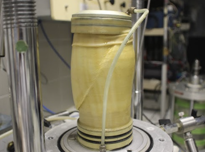
A triaxial latex membrane usually tears because of incorrect sizing, excessive installation strain, sharp contact points, specimen surface irregularities, material aging or unsuitable test conditions.
The location and appearance of the damage often provide the best evidence of its cause.
For example:
- a tear near the top cap may indicate a sharp edge, damaged O-ring or insufficient overlap;
- a longitudinal split through the specimen zone may indicate excessive circumferential stretch;
- a small puncture aligned with a coarse particle may indicate localized contact damage;
- random cracking during gentle stretching may indicate aging or chemical deterioration;
- repeated damage at the same apparatus position usually points to the equipment rather than the membrane batch.
Do not respond to every failure by simply choosing a thicker membrane. Greater thickness can improve puncture resistance, but it can also increase membrane restraint and influence the measured specimen response.
Important: Stop the test when membrane integrity is uncertain. Follow the applicable test standard, equipment instructions, safety requirements and laboratory quality procedure when investigating or repeating the test.
Quick Diagnosis Table
| Damage location or symptom | Most likely causes | First checks |
|---|---|---|
| Tear at the top cap | Sharp edge, poor alignment, damaged O-ring, insufficient overlap | Inspect top cap, groove, ring and membrane position |
| Tear at the pedestal | Burr, debris, trapped porous-stone edge, incorrect seal | Inspect pedestal, groove, stone and lower overlap |
| Long split at mid-height | Membrane too small, excessive expansion, aged material | Compare actual specimen and membrane diameters |
| Small isolated puncture | Angular particle, tool contact, local membrane defect | Match the hole to the specimen and apparatus |
| Multiple pinholes | Rough surface, contaminated stretcher, poor material condition | Inspect membrane under controlled extension |
| Tear while loading stretcher | Sharp stretcher edge, excessive force, unsuitable diameter | Inspect stretcher and confirm dimensions |
| Tear while removing stretcher | Vacuum not fully released, membrane sticking to stretcher | Check vacuum release and internal surface |
| Failure after cell pressure is applied | Pre-existing puncture, sharp particle, sealing damage | Inspect the failure position and installation record |
| Cracking during gentle stretching | Aging, ozone, heat, UV or chemical exposure | Check storage and material condition |
| Sticky, soft or swollen membrane | Chemical incompatibility or heat exposure | Review cell fluid, cleaning agents and storage |
| Cloudy, hard or poorly recovering membrane | Oxidation, aging or unsuitable storage | Reject the membrane and inspect the remaining stock |
| Failure always at the same location | Apparatus defect or repeated installation error | Inspect and isolate the corresponding component |
First Response After a Membrane Failure
When a tear or leak is detected:
- stop the test according to the laboratory procedure;
- make the apparatus safe;
- record the test stage and pressure condition;
- photograph the membrane before removing it where practical;
- mark the orientation of the specimen, membrane, top cap and pedestal;
- remove the membrane carefully;
- preserve it for inspection;
- record the damage location and shape;
- inspect the corresponding specimen and apparatus surfaces;
- determine the likely cause before repeating the test.
Do not discard the failed membrane immediately. Its position and fracture pattern may be the strongest evidence available.
Do not continue using data from a test with uncertain membrane integrity unless the applicable method and responsible engineer establish that the result remains valid.
Diagnose the Failure by Test Stage
The point at which failure occurs helps narrow the cause.
Failure Before Installation
If a new membrane cracks or tears during gentle inspection, likely causes include:
- aging;
- ozone exposure;
- ultraviolet exposure;
- excessive heat;
- chemical contamination;
- damage during packaging or transport;
- manufacturing defects;
- previous stretching.
Inspect additional membranes from the same package or batch.
If several show similar deterioration, quarantine the affected stock until the cause is determined.
Failure While Loading the Membrane Stretcher
Possible causes include:
- sharp stretcher edges;
- burrs or scratches;
- blocked vacuum holes;
- an undersized membrane;
- pulling with fingernails or tools;
- uneven rolling;
- excessive vacuum;
- rapid expansion;
- insufficient stretcher capacity.
A membrane that must be forced into the stretcher may not be compatible with the installation system.
Failure While Lowering the Stretcher
Possible causes include:
- insufficient clearance around the specimen;
- contact between the stretcher and specimen;
- protruding particles;
- misaligned top cap;
- displaced filter strips;
- tilted specimen;
- abrupt handling.
Soft cohesive specimens may be damaged even when the membrane remains intact. The specimen should therefore be inspected if the stretcher makes contact.
Failure While Releasing the Membrane
Possible causes include:
- uneven vacuum release;
- excessive membrane stretch;
- the membrane sticking to the stretcher;
- sharp particles at the specimen surface;
- a fold becoming concentrated at one point;
- poor alignment.
Release the membrane gradually and evenly. Do not pull one side down to correct a poorly positioned membrane.
Failure During O-Ring Installation
Possible causes include:
- damaged or hardened O-rings;
- incorrect O-ring dimensions;
- sharp installation tools;
- twisted seals;
- insufficient membrane overlap;
- debris in the groove;
- excessive localized stretch;
- sharp top-cap or pedestal edges.
A tear beneath an O-ring may not be visible after the seal is installed. Inspect the membrane and sealing components carefully before repeating the test.
Failure When Cell Pressure Is Applied
A membrane that survives installation but fails during pressurization may have:
- a small installation puncture;
- local thinning caused by overstretching;
- contact with an angular particle;
- damage beneath a seal;
- an existing pinhole;
- unsuitable pressure or chemical resistance;
- inadequate thickness for the specific surface condition.
The failure pressure alone does not identify the cause. Examine where the damage occurred and what contacted that area.
Failure During Consolidation or Shearing
Late failure may be related to:
- increasing specimen bulging;
- strain localization;
- membrane penetration around coarse particles;
- movement of filter strips;
- slow crack propagation;
- chemical deterioration;
- long-duration creep;
- temperature effects;
- slipping or movement near the end seals.
In a long CU or CD test, a very slow leak may affect volume-change or pore-pressure data before an obvious tear is found.
Diagnose the Failure by Location
Tears Near the Top Cap
Inspect:
- top-cap circumference;
- O-ring groove;
- drainage fitting;
- filter-paper edge;
- membrane overlap;
- top-cap alignment;
- loading-ram alignment.
A tilted top cap can create high membrane strain on one side.
If tears repeatedly occur at the same circumferential position, mark that position and inspect the corresponding hardware closely.
Tears Near the Base Pedestal
Inspect:
- pedestal edge;
- O-ring groove;
- porous-stone position;
- loose sand or debris;
- drainage port;
- lower membrane overlap;
- contact during cell assembly.
A particle trapped beneath an O-ring can create both a leakage path and a local cutting point.
Tears Through the Middle of the Specimen
Possible causes include:
- membrane diameter too small;
- excessive installation stretch;
- local specimen bulging;
- sharp or angular particles;
- nonuniform membrane thickness;
- aged or damaged material.
A long axial split is often associated with circumferential tension, but the failure pattern should be evaluated together with the specimen and membrane dimensions.
Isolated Pinholes
Small round or irregular punctures may be caused by:
- protruding grains;
- sharp inclusions;
- tool contact;
- rough porous stones;
- particles inside the stretcher;
- manufacturing inclusions;
- localized thinning.
Align the failed membrane with the specimen before removal where possible. This can show whether the puncture corresponds to a particular particle.
Damage at Several Random Locations
Multiple failures may indicate:
- aging;
- chemical degradation;
- unsuitable cleaning;
- poor storage;
- repeated reuse;
- contamination;
- widespread material defects.
When damage appears random, inspect unused membranes from the same batch before blaming the apparatus or specimen.
Check the Membrane Size
The membrane should fit the specimen, top cap, pedestal and sealing system.
It should not be chosen according to the triaxial cell’s internal diameter.
If the membrane is too small
Possible consequences include:
- excessive circumferential strain;
- difficult stretcher loading;
- local wall thinning;
- specimen disturbance;
- increased membrane force;
- mid-height splitting;
- reduced remaining deformation capacity.
If the membrane is too large
Possible consequences include:
- wrinkles;
- folds;
- trapped pockets;
- movement during assembly;
- poor sealing;
- local stress concentrations when folds flatten.
Check actual dimensions
Do not rely only on nominal labels. Record:
- actual specimen diameter;
- specimen height;
- membrane internal diameter;
- membrane length;
- nominal wall thickness;
- diameter and thickness tolerances where available;
- top-cap and pedestal dimensions;
- required sealing overlap.
There is no universal installation-stretch percentage suitable for every membrane compound and specimen.
For detailed sizing guidance, see How to Choose the Right Thickness and Size of Latex Membrane for Triaxial Tests.
Check the Membrane Thickness
Thickness selection requires a balance between durability and mechanical influence.
A thinner membrane may:
- conform easily;
- exert less restraint;
- be appropriate for small or soft specimens;
- be more vulnerable to puncture and handling damage.
A thicker membrane may:
- resist some forms of puncture;
- tolerate rough handling better;
- be more suitable for certain coarse specimens;
- exert greater restraint;
- require more attention to membrane correction.
Do not increase thickness until the failure mechanism is identified.
A thicker membrane will not correct:
- a sharp top-cap edge;
- a damaged O-ring;
- a burr inside the stretcher;
- an incorrectly aligned specimen;
- chemical incompatibility;
- poor storage.
It may only hide the original problem while increasing boundary effects.
Check the Specimen Surface
Specimen characteristics strongly influence puncture risk.
High-risk conditions include:
- angular gravel;
- crushed aggregate;
- weathered rock fragments;
- shells or hard inclusions;
- projecting particles;
- uneven trimmed surfaces;
- large surface voids;
- damaged specimen edges.
Any surface preparation must comply with the test method and preserve the intended specimen condition.
Do not remove meaningful particles, fill surface voids or reshape an undisturbed specimen merely to protect the membrane unless the procedure permits it.
If a protective layer or double membrane is considered, document its use and evaluate its effect on:
- membrane restraint;
- drainage;
- radial deformation;
- volume-change measurement;
- membrane penetration;
- stress correction.
Check the Membrane Stretcher
A membrane stretcher can repeatedly damage membranes without leaving an obvious mark on the apparatus.
Inspect it under strong lighting and by careful touch where safe.
Check:
- entry edge;
- internal surface;
- vacuum ports;
- joints;
- seals;
- scratches;
- burrs;
- dried residue;
- embedded particles;
- cracks;
- dimensional compatibility.
Do not automatically polish, file or modify test equipment. Unauthorized modification can change dimensions or create new defects.
If damage is found, remove the stretcher from service and repair or replace it under the laboratory’s equipment-control procedure.
Check the Top Cap, Pedestal and Porous Stones
Inspect every surface that may contact the membrane.
Top cap and pedestal
Check for:
- sharp edges;
- machining burrs;
- damaged coating;
- rough grooves;
- debris;
- corrosion;
- incorrect dimensions;
- misalignment.
Porous stones
Check for:
- chipped edges;
- protruding grains;
- incorrect seating;
- contamination;
- damage during cleaning.
A chipped porous stone can puncture the membrane near an end while appearing to be a membrane-quality problem.
Filter paper and side drains
Check for:
- sharp corners;
- folding;
- displacement;
- incorrect length;
- movement during membrane release.
Check the O-Rings
O-rings should be compatible with the groove and equipment configuration.
Reject O-rings that are:
- cracked;
- cut;
- flattened;
- hardened;
- stretched permanently;
- contaminated;
- incorrectly sized.
During installation:
- use an approved O-ring tool;
- avoid twisting;
- keep the membrane smooth beneath the seal;
- place the ring in its intended groove;
- avoid trapping particles;
- confirm sufficient membrane overlap.
The number and arrangement of O-rings should follow the equipment instructions or applicable procedure. “Always use two O-rings” is not a universal rule.
Check Vacuum-Stretcher Use
A vacuum stretcher should use only enough vacuum to provide the necessary clearance.
Excessive vacuum can:
- over-expand the membrane;
- create local thinning;
- draw the membrane sharply into vacuum ports;
- increase damage around existing defects;
- make release less controlled.
Also avoid keeping the membrane expanded longer than necessary.
If the membrane does not release:
- stop lifting the stretcher;
- confirm the vacuum is fully released;
- check for sticking;
- use the approved release procedure;
- do not pull the stretcher away abruptly.
For the complete installation sequence, see How to Install a Latex Membrane on a Triaxial Soil Specimen.
Should Lubricant Be Used?
Do not apply lubricant as a universal solution to membrane tearing.
A lubricant may:
- change membrane friction;
- contact the specimen;
- affect water content;
- interfere with sealing;
- damage the rubber;
- enter drainage lines;
- change chemical conditions.
Use a lubricant only when it is:
- permitted by the applicable method;
- recommended by the equipment procedure;
- compatible with the membrane;
- compatible with the specimen and fluids;
- applied in a controlled and documented manner.
For unsaturated or moisture-sensitive specimens, even water can alter the test condition.
Check Storage and Aging
Natural rubber latex can deteriorate through exposure to:
- ozone;
- oxygen;
- heat;
- ultraviolet light;
- direct sunlight;
- chemical vapors;
- oils and solvents;
- prolonged stretching;
- unsuitable packaging.
Signs of aging include:
- fine surface cracks;
- hardening;
- tackiness;
- cloudiness;
- discoloration;
- whitening;
- loss of elasticity;
- poor recovery;
- tearing during gentle stretching.
Store membranes according to supplier instructions, generally:
- in sealed suitable packaging;
- in a cool, dry and dark location;
- away from sunlight;
- away from heaters;
- away from ozone-producing electrical equipment;
- away from oils, solvents and sharp objects;
- without tension or compression.
Use a first-in, first-out inventory system where appropriate.
Check Chemical Compatibility
Cell fluid, pore fluid, cleaning agents or specimen contaminants can alter the membrane.
Possible effects include:
- swelling;
- softening;
- hardening;
- shrinkage;
- discoloration;
- loss of tensile strength;
- reduced elongation;
- increased permeability;
- cracking.
Do not assume that natural rubber, nitrile, silicone or another elastomer resists every laboratory fluid.
Compatibility depends on:
- exact compound;
- exact fluid;
- concentration;
- temperature;
- exposure time;
- strain;
- pressure.
If chemical damage is suspected, compare unused and exposed membranes and consult product-specific compatibility information.
Can Transparent Membranes Help?
A transparent or translucent membrane may make it easier to identify:
- folds;
- displaced filters;
- surface particles;
- local punctures;
- trapped pockets;
- top-cap misalignment.
Transparency does not improve puncture resistance by itself. It is an inspection feature, not a strength classification.
Read What Is a Transparent Latex Membrane for Triaxial Testing? for more information.
How to Distinguish a Membrane Leak from Another System Leak
Pressure or volume drift does not automatically prove that the membrane has failed.
Also inspect:
- drainage tubing;
- valves;
- connectors;
- pressure controllers;
- transducer fittings;
- cell seals;
- piston seals;
- burettes;
- porous connections;
- temperature stability.
A systematic isolation procedure is better than replacing parts at random.
Record:
- which pressure changed;
- the rate of change;
- valve positions;
- whether the specimen was draining;
- controller-volume movement;
- temperature;
- visible evidence;
- test stage.
Use only leak-check procedures approved for the apparatus and test method. An arbitrary bubble test or pressure step may disturb the specimen or violate the intended drainage condition.
Should a Torn Membrane Be Repaired?
For controlled triaxial testing, replacement is generally more appropriate than patching.
A repair can introduce:
- local thickening;
- uncertain stiffness;
- a new stress concentration;
- unreliable sealing;
- poor repeatability;
- difficulty applying corrections.
The important action is not merely replacing the membrane. Identify and correct the cause first, or the new membrane may fail in the same place.
Should a Membrane Be Reused?
A used membrane may have:
- permanent set;
- local thinning;
- small punctures;
- seal damage;
- chemical contamination;
- reduced recovery;
- invisible tear initiation.
Reuse should follow the applicable standard and laboratory policy.
For critical or long-duration testing, a new inspected membrane generally provides clearer traceability.
Corrective-Action Matrix
| Confirmed cause | Corrective action |
|---|---|
| Membrane too small | Select a compatible internal diameter and verify actual dimensions |
| Membrane too large | Select a closer fit and eliminate folds |
| Insufficient length | Use a membrane with adequate sealing overlap |
| Sharp apparatus edge | Remove component from service and repair under equipment control |
| Damaged porous stone | Replace or correctly reseat it |
| Damaged O-ring | Replace with the specified size and material |
| Excessive vacuum | Use only the vacuum required for clearance |
| Stretcher contamination | Clean using the approved compatible procedure |
| Angular specimen surface | Review specimen preparation and permitted protective options |
| Aging | Quarantine affected stock and improve storage |
| Chemical incompatibility | Select a verified compatible compound |
| Local thickness defect | Review batch inspection and supplier quality records |
| Repeated installation error | Update the procedure and retrain operators |
| Unknown cause | Do not change several variables at once; run a controlled investigation |
Failure Investigation Record
Use a consistent record for every failure:
Date:
Operator:
Test ID:
Test type:
Specimen material:
Specimen diameter:
Specimen height:
Maximum particle size:
Membrane material:
Membrane internal diameter:
Membrane length:
Nominal thickness:
Manufacturer:
Batch or lot:
Storage condition:
Membrane stretcher ID:
O-ring specification:
Cell fluid:
Pore fluid:
Temperature:
Test stage at failure:
Cell pressure at failure:
Back pressure at failure:
Axial strain at failure:
Damage location:
Damage shape:
Photograph reference:
Corresponding apparatus location:
Corresponding specimen feature:
Probable cause:
Corrective action:
Result of repeated test:
Patterns become easier to identify when failures are documented consistently.
Prevention Checklist
Before every installation, confirm:
- [ ] The actual specimen dimensions have been measured.
- [ ] The membrane diameter is compatible with the specimen.
- [ ] The membrane length provides adequate sealing overlap.
- [ ] The thickness is appropriate for the specimen and test.
- [ ] The membrane has been visually inspected.
- [ ] The membrane shows no aging or chemical damage.
- [ ] The stretcher is clean and undamaged.
- [ ] Vacuum ports are clear.
- [ ] The top cap and pedestal have no sharp edges.
- [ ] Porous stones are correctly seated and undamaged.
- [ ] Filter strips cannot cut or fold beneath the membrane.
- [ ] O-rings are correctly sized and in good condition.
- [ ] The specimen is centered and vertical.
- [ ] The membrane is released gradually and evenly.
- [ ] No major wrinkles remain.
- [ ] Seals are positioned according to the approved procedure.
- [ ] The completed assembly has been inspected.
- [ ] Leak checks follow the correct method.
- [ ] Membrane details are recorded.
Frequently Asked Questions
Why does my latex membrane tear at the top?
Common causes include a sharp top-cap edge, damaged O-ring, insufficient overlap, trapped filter paper or top-cap misalignment.
Why does it split down the middle?
A longitudinal mid-height split may be associated with excessive circumferential stretch, an undersized membrane, local thinning or aged rubber.
Why does it fail only after pressure is applied?
The membrane may contain a small puncture or thinned area that opens under pressure. Angular particles and damage beneath an O-ring are also possible causes.
Should I use a thicker membrane?
Only after identifying the failure mechanism. A thicker membrane may improve puncture resistance but can increase boundary restraint.
Can I lubricate the membrane?
Only if the applicable procedure permits it and compatibility has been confirmed. Lubricants can contaminate the specimen, alter friction or damage the membrane.
Can rough soil be wrapped with two membranes?
A double-membrane arrangement may reduce leakage risk in some applications, but it also increases thickness and restraint. Use it only when technically justified and permitted.
Can a small hole be patched?
Replacement is generally preferred because a patch creates an uncertain local boundary.
Is every membrane failure a manufacturing defect?
No. Failures may result from sizing, apparatus damage, specimen particles, installation, storage, chemicals or material defects. Preserve and inspect the failed membrane before assigning the cause.
Why do several membranes tear at the same position?
Repeated failure at the same position strongly suggests a corresponding apparatus feature or repeated installation step. Inspect that location before using another membrane.
Can membrane aging occur in unopened packaging?
Yes. Packaging can slow exposure but does not stop all aging. Storage time, heat, ozone and packaging condition still matter.
Conclusion
Repeated latex membrane tearing should be treated as a diagnosable test-system problem.
The most reliable investigation considers:
- where the damage occurred;
- when it occurred;
- what the membrane contacted;
- how much it was stretched;
- the specimen surface;
- the membrane dimensions and thickness;
- the condition of the stretcher, top cap, pedestal and O-rings;
- storage and chemical exposure;
- whether the failure repeats in the same pattern.
Do not automatically solve every tear by increasing membrane thickness. Correct sizing, controlled installation, undamaged hardware and suitable storage often matter more.
Once the cause has been identified, change one relevant factor at a time and document the result. This produces a repeatable corrective action instead of a temporary workaround.