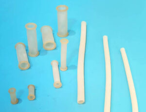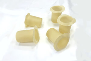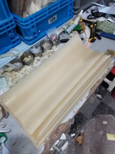
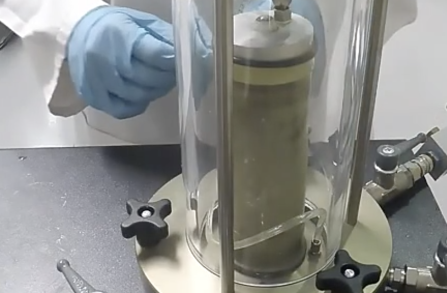
Correct latex membrane installation is essential for maintaining a sealed and controlled boundary around a triaxial soil specimen.
A membrane that is punctured, overstretched, wrinkled or poorly sealed can allow cell fluid to contact the specimen. It can also interfere with saturation, consolidation, pore-pressure measurement and volume-change data.
The basic installation process is:
- confirm the specimen and membrane dimensions;
- inspect the specimen, membrane and apparatus;
- place the specimen on the pedestal;
- load the membrane into a suitable stretcher;
- expand the membrane without excessive strain;
- lower the stretcher over the specimen;
- release the membrane evenly;
- position the top cap;
- seal the membrane at both ends;
- inspect the assembly and complete the required leak checks.
The exact procedure should follow the applicable test standard, equipment instructions and laboratory quality system.
Important: This guide provides general installation principles. It does not replace the current ASTM, ISO, BS or other applicable test method.
Why Correct Membrane Installation Matters
The latex membrane separates two controlled environments:
- the specimen and its drainage system;
- the pressurized fluid inside the triaxial cell.
Drainage should occur only through the intended drainage lines, porous stones and other approved drainage components.
Incorrect installation can cause:
- cell fluid entering the specimen;
- leakage from the specimen drainage system;
- unreliable pore-pressure measurements;
- apparent volume change unrelated to the soil;
- unstable back pressure;
- membrane puncture during confinement;
- specimen disturbance;
- nonuniform boundary restraint;
- premature termination of the test.
Some installation problems cause immediate failure. Others create small measurement errors that may not become obvious until the data are analyzed.
Components of a Typical Triaxial Specimen Assembly
A conventional assembly may include:
- base pedestal;
- lower porous stone;
- lower filter paper, when required;
- cylindrical soil specimen;
- upper filter paper, when required;
- upper porous stone;
- top cap;
- latex membrane;
- membrane stretcher;
- O-rings or approved sealing bands;
- drainage lines;
- pore-pressure connection;
- side drains or filter strips, when required.
The exact components depend on the soil, apparatus and selected UU, CU or CD procedure.
Tools and Materials
Prepare everything before exposing or handling the specimen.
| Tool or component | Purpose |
|---|---|
| Correctly sized latex membrane | Separates the specimen from cell fluid |
| Membrane stretcher | Expands the membrane for installation |
| Controlled vacuum source | Expands the membrane in a vacuum stretcher |
| Suitable O-rings | Seal the membrane at the pedestal and top cap |
| O-ring installation tool | Reduces damage during seal placement |
| Caliper or diameter tape | Confirms specimen dimensions |
| Ruler or height-measurement device | Confirms specimen height |
| Porous stones | Provide drainage at specimen ends |
| Filter paper | Used when required by the procedure |
| Side drains or filter strips | Used when required for drainage |
| Top cap and pedestal | Support and connect the specimen |
| Clean, approved working materials | Reduce contamination and handling damage |
| Camera or inspection light | Documents and reveals installation defects |
Do not introduce a lubricant, powder or cleaning chemical unless it is permitted by the test method and shown to be compatible with the membrane and specimen.
Water used casually as a lubricant can change the moisture condition of an unsaturated or moisture-sensitive specimen.
Step 1: Review the Test Requirements
Before choosing the membrane, identify:
-
test type: UU, CU or CD;
-
specimen material;
-
specimen diameter;
-
specimen height;
-
expectedACLE? Need no typos. Continue.
-
expected axial strain;
-
maximum cell pressure;
-
back pressure;
-
test duration;
-
cell fluid;
-
pore fluid;
-
particle size and/be. Need fix whole text internally. Let’s keep.
-
particle size and angular melt Bewerbung? Need careful. I need produce flawless. Let’s restart from Step 1 in final mental and continue.
-
particle size and angularity;
-
applicable membrane correction;
-
required drainage components.
Long-duration CU and CD tests place more emphasis on slow leakage, seal stability and aging than a short UU test.
Coarse or angular specimens present a greater puncture risk than smooth cohesive specimens.
Step 2: Measure the Specimen
Measure the specimen according to the applicable method.
Record:
- average diameter;
- initial height;
- mass, where required;
- visible defects;
- surface irregularities;
- specimen identification.
The membrane should fit the specimen assembly, not the inside diameter of the pressure cell.
If the membrane is too small, installation may cause:
- excessive stretching;
- local wall thinning;
- increased membrane tension;
- specimen compression;
- tearing or puncture.
If it is too large, it may cause:
- wrinkles;
- folds;
- trapped pockets;
- inconsistent contact;
- sealing difficulties.
Do not use an arbitrary percentage of initial stretch as a universal rule. Acceptable fit depends on the membrane material, thickness, tolerances, specimen condition and approved procedure.
Step 3: Select the Membrane Length and Thickness
The membrane must be long enough to:
- cover the full specimen;
- extend over the base pedestal;
- extend over the top cap;
- reach all required O-ring positions;
- maintain sealing overlap during deformation.
A membrane that is too short can pull away from a seal as the specimen shortens or bulges. An unnecessarily long membrane can create folds near the specimen ends.
Thickness selection requires a balance.
A thinner membrane may produce less mechanical restraint but may be more vulnerable to handling damage and puncture.
A thicker membrane may be more durable but can add greater restraint to a small or soft specimen.
For detailed selection guidance, see How to Choose the Right Thickness and Size of Latex Membrane for Triaxial Tests.
Step 4: Inspect the Latex Membrane
Inspect every membrane before installation, even if it is new.
Under adequate lighting, check for:
- pinholes;
- cuts;
- tears;
- cracks;
- thin spots;
- thick spots;
- permanent folds;
- surface contamination;
- sticky areas;
- hardened areas;
- embedded particles;
- damage at either open end;
- poor elastic recovery.
A gentle, controlled extension may reveal pinholes or cracks that are difficult to see when the membrane is relaxed. Do not overstretch it during inspection.
Reject the membrane if its condition is uncertain. The cost of replacing a membrane is normally much lower than the cost of repeating a failed test.
Step 5: Inspect the Membrane Stretcher
The stretcher must be clean, smooth and compatible with the specimen size.
Check for:
- sharp edges;
- burrs;
- scratches;
- cracks;
- blocked vacuum holes;
- damaged seals;
- loose particles;
- excessive internal roughness;
- moisture or chemical residue.
A small burr can cut the membrane while it is being expanded. A blocked vacuum port can cause uneven expansion and make the membrane difficult to release.
The stretcher’s internal dimensions must provide sufficient clearance over the complete specimen assembly without requiring excessive membrane expansion.
Step 6: Inspect the Pedestal and Top Cap
Clean and inspect all surfaces that contact the membrane.
Pay particular attention to:
- O-ring grooves;
- pedestal edges;
- top-cap edges;
- drainage ports;
- porous-stone edges;
- filter-paper corners;
- side-drain edges.
Sharp edges or displaced filter material can puncture the membrane after cell pressure is applied.
Confirm that:
- drainage lines are connected correctly;
- valves are in the required initial positions;
- porous stones are prepared according to the procedure;
- top and bottom interfaces are level;
- O-rings are the correct size and condition.
Do not use cracked, hardened, oversized or undersized O-rings.
Step 7: Prepare the Specimen Surface
Cohesive specimens
For an intact or trimmed cohesive specimen:
- minimize handling;
- prevent moisture loss;
- avoid pressing or reshaping the surface;
- remove loose trimming debris;
- keep the specimen ends parallel;
- protect soft edges from damage.
Do not smooth away natural fissures or alter the specimen structure merely to make membrane installation easier.
Granular specimens
A reconstituted granular specimen may be formed inside a split mold or by another approved preparation method.
Before releasing the mold:
- confirm that the specimen is stable;
- check the membrane and mold position;
- verify the top cap and pedestal alignment;
- confirm that filter strips are correctly positioned;
- avoid disturbing the target density.
Angular or protruding particles can create local puncture points. Any surface treatment or protective arrangement must be permitted by the test procedure and documented.
Step 8: Position the Lower Components
Place the required lower components on the pedestal in the correct order.
These may include:
- lower porous stone;
- lower filter paper;
- specimen;
- side drains or filter strips, where required.
Center the specimen on the pedestal.
Check alignment from more than one direction. An off-center specimen can:
- contact the stretcher;
- place uneven strain on the membrane;
- tilt the top cap;
- encourage nonuniform deformation;
- damage the specimen during cell assembly.
Step 9: Load the Membrane into the Stretcher
The exact method depends on the stretcher design.
For a vacuum-type stretcher:
- inspect the membrane orientation;
- insert the membrane into the stretcher;
- fold or roll the ends over the stretcher as designed;
- confirm that the membrane is evenly positioned;
- apply only enough vacuum to draw the membrane against the stretcher wall.
Avoid:
- twisting the membrane;
- pulling one side more than the other;
- using fingernails or sharp tools;
- applying excessive vacuum;
- stretching the membrane for longer than necessary.
If the membrane does not expand evenly, stop and investigate. Do not force the stretcher over the specimen.
Possible causes include an undersized membrane, blocked vacuum holes, leakage in the stretcher or incorrect loading.
Step 10: Lower the Stretcher Over the Specimen
Hold the stretcher vertically and lower it slowly over the centered specimen.
Maintain clearance between:
- membrane and specimen surface;
- stretcher and top cap;
- stretcher and pedestal;
- membrane and sharp particles.
Do not allow the stretcher to:
- scrape the specimen;
- compress the top surface;
- displace filter strips;
- tilt the top cap;
- knock the specimen out of alignment.
Soft clay specimens can be disturbed by very small contact forces. Granular specimens may lose material or change density if the assembly is struck.
If contact occurs, stop and inspect the specimen before proceeding.
Step 11: Position the Top Components
Install the required upper filter paper and porous stone, followed by the top cap, according to the approved sequence.
Confirm that the top cap:
- is centered;
- sits level;
- makes proper contact;
- does not trap a folded filter strip;
- does not create a sharp edge beneath the membrane;
- aligns with the loading ram.
Do not use the membrane to pull an incorrectly positioned top cap into alignment.
Step 12: Release the Membrane Evenly
Release the vacuum gradually so the membrane moves toward the specimen.
Watch for:
- folds;
- twisting;
- trapped air;
- displaced filter strips;
- excessive tension;
- localized stretching;
- movement of the specimen.
Allow the membrane to contact the specimen evenly.
If a major fold becomes trapped, do not aggressively drag the membrane across a soft specimen. Re-expand the membrane and repeat the placement if the procedure and specimen condition permit.
A transparent membrane can make folds, filter-strip movement and trapped pockets easier to observe. Learn more in What Is a Transparent Latex Membrane for Triaxial Testing?.
Step 13: Remove the Stretcher
After the membrane has been released:
- confirm that it is not attached to the stretcher wall;
- raise the stretcher vertically;
- avoid dragging it across the membrane;
- keep the specimen and top cap aligned;
- inspect the membrane immediately.
If the membrane rises with the stretcher, stop. Do not pull the stretcher away abruptly.
Reapply controlled vacuum or adjust the membrane according to the equipment procedure.
Step 14: Arrange the Membrane at Both Ends
The membrane should extend smoothly over the pedestal and top cap.
Before installing O-rings, confirm:
- sufficient overlap;
- no twisted membrane;
- no fold beneath the sealing location;
- clean sealing surfaces;
- correct top-cap position;
- correct drainage-component position.
Avoid excessive membrane buildup beneath the O-rings. Multiple folds can prevent uniform sealing and create local stress concentrations.
Step 15: Install the O-Rings
Use the O-ring size, number and position specified by the equipment or test procedure.
A general sequence is:
- expand the O-ring using the correct tool;
- position it over the designated groove;
- release it without twisting;
- confirm that the membrane lies smoothly beneath it;
- repeat for the remaining required seals.
Do not roll an O-ring across the specimen surface using a sharp tool.
Check that each O-ring:
- sits in its intended groove;
- is not twisted;
- has not cut the membrane;
- does not trap debris;
- provides continuous contact;
- has not displaced the top cap or specimen.
Using two O-rings at each end may be required by some procedures or equipment configurations, but it should not be presented as a universal rule.
Step 16: Inspect the Completed Assembly
Inspect the assembly from all sides before installing the cell chamber.
Check:
- specimen verticality;
- top-cap alignment;
- membrane contact;
- folds and wrinkles;
- trapped pockets;
- filter-strip position;
- membrane overlap;
- O-ring position;
- visible punctures;
- drainage connections.
Photographing the completed assembly can provide useful test documentation.
Include the specimen identification in the photograph where practical.
Step 17: Assemble the Triaxial Cell
Install the cell wall and loading components according to the equipment instructions.
During cell assembly:
- avoid striking the specimen;
- do not snag pressure or drainage lines;
- confirm that the loading ram is aligned;
- check all cell seals;
- use the correct cell fluid;
- remove trapped cell air as required;
- secure the cell safely.
Do not begin pressurization until the apparatus is fully assembled and checked.
Step 18: Complete the Required Leak Checks
Leak testing should follow the laboratory procedure and must not unintentionally alter the specimen’s required initial condition.
Possible checks include:
- pressure-system stability;
- drainage-line stability;
- visible inspection;
- controller-volume stability;
- back-pressure-system checks;
- transducer-zero checks;
- valve-function checks.
Do not apply an arbitrary vacuum or pressure directly to the specimen merely to see whether the membrane leaks. The check must remain compatible with the selected UU, CU or CD procedure.
Warning signs include:
- unexplained pressure loss;
- continuing controller-volume change without a test-related cause;
- fluid appearing in the wrong line;
- bubbles or visible fluid movement;
- inability to maintain back pressure;
- pore-pressure drift;
- cell fluid entering the specimen system.
Pressure drift does not automatically prove membrane leakage. Also check valves, tubing, connectors, controllers, seals and temperature stability.
Installation Differences for UU, CU and CD Tests
UU testing
In a UU test, drainage is normally prevented during application of cell pressure and shearing.
Installation priorities include:
- minimizing specimen disturbance;
- maintaining the intended moisture condition;
- reliable membrane isolation;
- correct valve status;
- avoiding unnecessary delays.
A leak can invalidate the intended undrained boundary.
CU testing
A CU test includes consolidation before undrained shearing. Pore pressure may also be measured.
Installation priorities include:
- reliable drainage connections;
- leak-free back-pressure lines;
- secure membrane seals;
- correct filter and side-drain placement;
- maintaining isolation during saturation and consolidation;
- preventing slow leakage during shearing.
Small leaks can affect saturation assessment, consolidation measurements and effective-stress interpretation.
CD testing
A CD test permits drainage during consolidation and shearing.
Because drained shearing may be slow, priorities include:
- long-duration seal stability;
- stable membrane properties;
- reliable volume-change measurement;
- temperature control;
- chemical compatibility;
- distinguishing drainage from leakage.
Common Installation Problems
| Observation | Possible cause | Recommended action |
|---|---|---|
| Membrane tears while loading the stretcher | Sharp stretcher edge, aged membrane or excessive stretch | Stop, inspect the stretcher and replace the membrane |
| Membrane will not expand evenly | Blocked vacuum port, poor seal or incorrect size | Check the stretcher and membrane dimensions |
| Specimen is compressed during placement | Insufficient stretcher clearance | Remove the stretcher carefully and use a suitable setup |
| Large wrinkles remain | Membrane too large or released unevenly | Reinstall with the correct size if specimen condition permits |
| Membrane lifts with the stretcher | Vacuum not fully released or surface sticking | Stop and release it gradually |
| O-ring cuts the membrane | Sharp tool, damaged ring or incorrect installation | Replace damaged components and membrane |
| Top cap tilts | Misalignment, uneven specimen end or trapped filter | Stop and correct before cell assembly |
| Pressure cannot be maintained | Membrane, cell, line, valve or connector leak | Isolate and test each system component |
| Unexpected volume change continues | Leakage, air, temperature drift or controller issue | Diagnose before assuming soil behavior |
| Membrane punctures under pressure | Angular particle, thin spot or installation damage | Stop the test and investigate the puncture location |
What to Do If the Membrane Is Punctured
For controlled triaxial testing, replacing a punctured membrane is generally more appropriate than attempting to patch it.
A repair can introduce:
- uncertain stiffness;
- local thickening;
- unreliable sealing;
- a new stress concentration;
- poor repeatability.
Before repeating the test, identify the location and likely cause.
Puncture near the specimen surface
Check for:
- angular particles;
- protruding inclusions;
- local membrane thinning;
- excessive installation stretch;
- unsuitable thickness.
Damage near the top cap or pedestal
Check for:
- sharp edges;
- damaged O-ring grooves;
- incorrect overlap;
- twisted O-rings;
- trapped debris;
- filter-paper corners.
Damage corresponding to the stretcher
Check for:
- burrs;
- scratches;
- blocked vacuum ports;
- rough internal surfaces;
- excessive vacuum.
For a detailed troubleshooting guide, see Why Your Latex Membrane Keeps Tearing and How to Fix It.
How Installation Can Affect Test Results
An intact membrane can still influence results if it is poorly selected or installed.
Mechanical restraint
As the specimen expands, the membrane stretches and adds resistance. The effect depends on membrane thickness, stiffness, specimen diameter and strain.
Membrane penetration
In granular specimens, cell pressure may push the membrane into surface voids. This can affect measured volume change.
Read Membrane Penetration Effect in Triaxial Testing Explained.
Wrinkles
Folds may change local contact and can create unstable volume changes as they flatten or move.
End restraint
Membrane overlap and O-rings create locally stiffer zones near the specimen ends. End-platen friction can create an additional, separate boundary effect.
Leakage
Leakage can alter pore pressure, drainage and volume-change measurements. It may invalidate the assumed test condition even if the cell pressure appears stable.
Should a Membrane Be Reused?
Reuse can introduce uncertainty caused by:
- permanent stretching;
- localized thinning;
- small punctures;
- sealing damage;
- contamination;
- aging;
- loss of elastic recovery.
Follow the applicable standard and laboratory policy.
For critical, long-duration or high-value testing, a new inspected membrane generally provides better traceability.
If reuse is permitted, the membrane should be:
- cleaned using a compatible procedure;
- dried without damaging heat;
- inspected under good lighting;
- checked for permanent deformation;
- checked for pinholes and cracks;
- linked to an appropriate usage record.
Installation Record
For each test, consider recording:
Specimen ID:
Test type:
Specimen material:
Specimen diameter:
Specimen height:
Membrane material:
Membrane internal diameter:
Membrane length:
Nominal wall thickness:
Manufacturer:
Batch or lot number:
Date opened:
Visual inspection result:
Membrane stretcher ID:
O-ring size and number:
Filter or side-drain arrangement:
Installation observations:
Leak-check result:
Cell fluid:
Maximum cell pressure:
Operator:
Photograph reference:
This information helps investigate unexpected results and compare repeatability between test series.
Pre-Test Checklist
Before applying cell pressure, confirm:
- [ ] The specimen dimensions have been recorded.
- [ ] The membrane dimensions match the specimen assembly.
- [ ] The membrane has no visible defects.
- [ ] The stretcher is clean and free from sharp edges.
- [ ] The pedestal and top cap are clean.
- [ ] Porous stones and filters are correctly positioned.
- [ ] The specimen is centered and vertical.
- [ ] The top cap is aligned.
- [ ] The membrane has sufficient end overlap.
- [ ] There are no major wrinkles or folds.
- [ ] O-rings are correctly positioned and not twisted.
- [ ] Drainage lines are connected correctly.
- [ ] Valves are in the required initial positions.
- [ ] Transducers and controllers have been checked.
- [ ] The cell is assembled securely.
- [ ] The required leak checks have been completed.
- [ ] The assembly has been documented.
Frequently Asked Questions
What is the purpose of the latex membrane?
It separates the specimen and pore fluid from the triaxial cell fluid while allowing confining pressure to act through a flexible boundary.
Should the membrane match the specimen or the triaxial cell?
It should primarily match the specimen, top cap, pedestal and sealing arrangement—not the cell’s internal diameter.
How tight should the membrane be?
It should fit without major folds but should not require excessive or damaging stretch. There is no universal fit percentage suitable for every membrane and specimen.
Can water be used to help installation?
Only if it is permitted by the test procedure and will not alter the specimen condition. Casual use of water can affect moisture-sensitive or unsaturated specimens.
How many O-rings should be used?
Use the number and arrangement specified by the equipment, standard or approved laboratory procedure. Do not assume that one configuration applies to every apparatus.
How can I tell whether the membrane is leaking?
Possible signs include pressure instability, unexplained volume change, fluid in the wrong line and inability to maintain back pressure. The entire pressure and drainage system must be checked because these signs can have other causes.
Can a punctured membrane be patched?
Replacement is generally more appropriate for controlled testing because a patch creates an uncertain local boundary.
Why does the membrane wrinkle?
Common causes include excessive membrane diameter, uneven release, twisting and unnecessary membrane length.
Why does the membrane keep tearing during installation?
Possible causes include an undersized membrane, aged rubber, excessive vacuum, sharp stretcher edges, damaged O-rings or angular particles.
Does a thicker membrane solve puncture problems?
Not always. It may improve puncture resistance but also increase specimen restraint. The cause of the puncture should be identified before changing thickness.
Can installation change the measured strength?
Yes. Excessive membrane tension, folds, leakage and specimen disturbance can influence the measured response.
Conclusion
Installing a latex membrane correctly requires more than stretching a rubber tube over a specimen.
Reliable installation depends on:
- correct specimen and membrane dimensions;
- appropriate membrane thickness;
- careful inspection;
- a clean and suitable membrane stretcher;
- protected specimen surfaces;
- correct top-cap and pedestal alignment;
- smooth membrane release;
- properly positioned O-rings;
- verified drainage connections;
- appropriate leak checks;
- complete test documentation.
The best installation is one that maintains a sealed boundary without damaging the specimen or introducing unnecessary membrane strain.
When an installation problem occurs, stop and identify its cause before beginning the test. Replacing a damaged membrane and correcting the setup is more reliable than continuing with an uncertain specimen boundary.