A triaxial test is a laboratory method used to evaluate the strength, deformation, pore-pressure response and volume-change behavior of soil under controlled stress and drainage conditions.
A cylindrical soil specimen is enclosed in a flexible membrane and installed inside a pressurized cell. The pressure in the cell applies radial confinement, while a loading frame applies axial compression.
By controlling specimen saturation, consolidation, drainage, cell pressure and axial loading, the laboratory can investigate how soil behaves under different stress paths.
Triaxial test results may be used in the analysis of:
- Foundations
- Slopes
- Embankments
- Earth dams
- Retaining structures
- Excavations
- Tunnels
- Offshore foundations
- Landfills
- Seismic and cyclic loading
- Constitutive soil models
The test is more versatile than a simple unconfined or direct shear test because it allows the laboratory to control confining stress and drainage conditions and, in many test types, measure pore-water pressure and volume change.
Important: This article is a technical overview. It does not replace ASTM, ISO, BS or another applicable test standard. Laboratories should obtain the current standard and follow their approved specimen-preparation, calibration, testing and reporting procedures.
What Is a Triaxial Test?
In a conventional triaxial compression test, the specimen is subjected to an approximately axisymmetric stress condition.
The two radial principal stresses are normally equal:
[
\sigma_2 = \sigma_3
]
Axial loading increases the major principal stress, (\sigma_1), while the cell-pressure system controls the radial confining stress, (\sigma_3).
The difference between the axial and confining principal stresses is commonly called deviator stress:
[
q = \sigma_1 – \sigma_3
]
For saturated soil, effective stress is calculated using pore-water pressure:
[
\sigma’ = \sigma – u
]
where:
- (\sigma’) is effective stress;
- (\sigma) is total stress;
- (u) is pore-water pressure.
The soil skeleton’s strength and deformation are governed primarily by effective stress. The pore-pressure response is therefore especially important in undrained testing.
Why Is It Called a Triaxial Test?
The name refers to the three principal stress directions acting on the specimen.
In a conventional axisymmetric triaxial test:
- One principal stress acts along the specimen axis.
- Two equal principal stresses act in the radial directions.
This is different from a true triaxial apparatus, which can control three unequal principal stresses independently.
A conventional triaxial test should therefore not be described as applying three independently controlled pressures.
What Does a Triaxial Test Measure?
Depending on the test type and apparatus, measurements may include:
- Axial load
- Axial deformation
- Cell pressure
- Back pressure
- Pore-water pressure
- Drainage volume
- Specimen volume change
- Radial deformation
- Local strain
- Time
- Temperature
These measurements may be used to calculate or interpret:
- Axial strain
- Deviator stress
- Total principal stresses
- Effective principal stresses
- Stress–strain behavior
- Pore-pressure response
- Effective stress paths
- Total stress paths
- Peak strength
- Critical-state behavior
- Residual or post-peak behavior
- Stiffness
- Dilatancy
- Volumetric strain
- Strength envelopes
Not every test produces every parameter. The available results depend on drainage conditions, instrumentation, specimen quality and the test program.
Total Stress and Effective Stress
Understanding the difference between total and effective stress is fundamental to triaxial testing.
Total Stress
Total stress represents the force acting over the total area.
Cell pressure and axial load are used to determine the total stresses applied to the specimen.
Pore-Water Pressure
In saturated soil, water in the voids carries part of the applied stress.
If loading occurs without drainage, pore-water pressure may increase or decrease depending on the soil and stress path.
Effective Stress
Effective stress represents the stress carried by the soil skeleton.
For saturated soil:
[
\sigma’ = \sigma – u
]
A change in pore pressure can therefore change effective stress even if total stress remains constant.
This is why pore-pressure measurement is essential in many consolidated undrained tests.
Main Types of Triaxial Tests
The three commonly discussed test types are UU, CU and CD.
| Feature | UU | CU | CD |
|---|---|---|---|
| Full name | Unconsolidated Undrained | Consolidated Undrained | Consolidated Drained |
| Saturation stage | Not normally a separate standard stage | Yes | Yes |
| Consolidation before shear | No | Yes | Yes |
| Drainage during shear | Closed | Closed | Open |
| Pore-pressure measurement | Not normally a primary standard output | Yes | Not normally central to drained-strength interpretation |
| Main interpretation | Total stress | Total and effective stress | Effective stress |
| Relative duration | Usually shortest | Longer | Usually longest |
UU—Unconsolidated Undrained Test
In a UU test:
- The specimen is not allowed to consolidate under the applied cell pressure.
- Drainage is prevented when confining pressure is applied.
- Drainage remains closed during axial shearing.
- Axial load and deformation are measured.
- Results are primarily interpreted using total stress.
UU testing is commonly associated with ASTM D2850 for cohesive soils.
“Unconsolidated” describes the laboratory procedure. It does not mean that the field soil has never experienced geological or engineering consolidation.
UU testing is normally used when a relatively rapid total-stress assessment is required and the selected laboratory stress path is appropriate for the field problem.
CU—Consolidated Undrained Test
In a CU test:
- The specimen is saturated.
- It is consolidated under the selected effective stress.
- Drainage is closed.
- Axial shearing is performed without intentional drainage.
- Pore-water pressure is measured.
This allows both total-stress and effective-stress behavior to be evaluated.
CU testing may be appropriate when soil has consolidated under an existing stress condition and is then subjected to loading without sufficient time for drainage.
ASTM D4767 covers consolidated undrained triaxial compression testing of saturated cohesive soils under its defined conditions.
CD—Consolidated Drained Test
In a CD test:
- The specimen is saturated.
- It is consolidated.
- Drainage remains open during shearing.
- Axial loading is slow enough to maintain the required drained condition.
- Drainage or volume change is measured.
CD testing is used to evaluate drained effective-stress strength and volumetric behavior.
Because low-permeability soil drains slowly, a CD test can take considerably longer than a UU or CU test.
ASTM D7181 is commonly associated with consolidated drained triaxial compression testing of soils.
Which Triaxial Test Should Be Used?
Test selection should be based on the engineering question.
| Engineering requirement | Possible test direction |
|---|---|
| Rapid total-stress undrained assessment | UU |
| Undrained response after consolidation | CU |
| Pore-pressure response during undrained loading | CU |
| Effective stress path during undrained loading | CU |
| Drained strength | CD |
| Volume change during drained shearing | CD |
| Both short-term and long-term behavior | A coordinated program using multiple test types |
| Complex stress history | Specialized stress-path testing |
The final selection should consider:
- Soil type
- Soil permeability
- Degree of saturation
- Stress history
- Field drainage conditions
- Loading rate
- In-situ effective stress
- Required design parameters
- Project specification
- Applicable standard
A test should not be selected merely because it is the fastest or because the equipment is already available.
Triaxial Test Equipment
A triaxial system may include:
- Axial loading frame
- Triaxial pressure cell
- Cell-pressure controller
- Back-pressure controller
- Pore-pressure transducer
- Volume-change measurement system
- Load cell
- Axial displacement transducer
- Local strain sensors
- Data-acquisition system
- De-aired water system
- Drainage tubing and valves
- Pedestal and top cap
- Porous stones
- Filter materials
- Latex membrane
- Membrane stretcher
- O-rings
- Specimen-preparation tools
The required components depend on the test type.
A basic UU system may not require the same saturation, back-pressure and pore-pressure components as a full CU system.
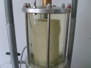
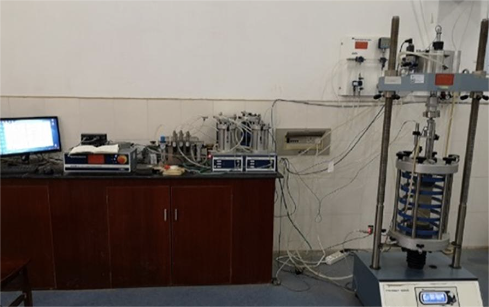
Figure 1. Replace this placeholder with an original labeled photograph showing the cell, loading frame, pressure controllers and data-acquisition system.
The Triaxial Cell
The triaxial cell contains:
- Cell base
- Chamber wall
- Cell top
- Loading ram
- Pedestal
- Top cap
- Pressure inlet
- Drainage connections
- Seals
- Cell fluid
Its functions include:
- Containing the pressurized cell fluid
- Applying radial confinement
- Transmitting axial load
- Supporting drainage and pore-pressure connections
- Allowing observation of the specimen assembly
The cell must have an appropriate pressure rating and enough internal clearance for the specimen and deformation expected during testing.
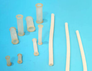
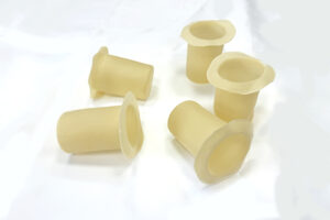
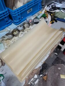
The Latex Membrane
The latex membrane surrounds the specimen and separates it from the cell fluid.
Its functions are to:
- Isolate the specimen
- Maintain intended drainage boundaries
- Allow confining pressure to act around the specimen
- Accommodate specimen deformation
- Help support weak specimens during handling
The membrane must have:
- Suitable material
- Correct inside diameter
- Sufficient length
- Appropriate thickness
- Reliable end sealing
- Acceptable dimensional uniformity
- No visible holes or damage
Membrane selection and installation can affect the test through:
- Leakage
- Membrane restraint
- Membrane penetration
- Wrinkles
- End-seal movement
- Specimen disturbance
Specimen Dimensions
Specimen dimensions are determined by the applicable standard, sampling method, material particle size and available apparatus.
Common laboratory specimens may have height-to-diameter ratios near 2, but this should not be treated as a universal requirement without consulting the relevant method.
Possible diameters include:
- 38 mm
- 50 mm
- 70 mm
- 100 mm
- 150 mm
- Larger custom dimensions
The selected diameter must be compatible with:
- Maximum particle size
- Specimen preparation
- Triaxial cell
- Pedestal
- Top cap
- Membrane
- Load capacity
- Pressure-control system
A larger specimen requires more material and a larger apparatus but may better represent coarse-grained soil.
Specimen Preparation
Specimen quality strongly affects triaxial test reliability.
Specimens may be:
- Intact
- Remolded
- Reconstituted
- Compacted
- Sedimented
- Pluviated
- Prepared by another defined method
Before testing, record as required:
- Specimen identification
- Sampling orientation
- Diameter
- Height
- Mass
- Moisture content
- Density
- Preparation method
- Disturbance
- Visible defects
Check the ends for:
- Flatness
- Parallelism
- Surface damage
- Loose particles
- Poor contact with porous stones
Do not repair, trim or smooth a specimen in a way that violates the applicable procedure.
Mounting the Specimen
A typical mounting sequence includes:
- Clean the pedestal and top cap.
- Prepare porous stones and filter materials.
- Position the specimen centrally.
- Inspect the latex membrane.
- Load the membrane into a stretcher.
- Expand it using the approved method.
- Lower it over the specimen.
- Release it evenly.
- Install the top cap.
- Seal both ends with O-rings.
- Connect the drainage lines.
- Check alignment and leakage.
The membrane should not be dragged directly over a fragile specimen.
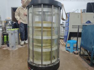
Figure 2. Replace this placeholder with original photographs of your specimen-mounting procedure.
System Preparation
Before pressurization:
- Verify calibration status.
- Confirm sensor ranges.
- Check valve positions.
- De-air pressure and drainage lines where required.
- Check fittings and tubing.
- Confirm load-frame alignment.
- Zero the sensors according to the procedure.
- Enter the correct specimen dimensions.
- Check the membrane and O-ring seals.
- Confirm the cell is assembled safely.
A pressure-system leak can be mistaken for specimen drainage or membrane failure.
The apparatus should be checked systematically before rejecting a membrane or specimen.
Saturation
Saturation is normally required for CU and CD testing of saturated soils.
The objective is to reduce or eliminate free air in the specimen and drainage system so that pore-pressure measurements and effective-stress calculations are reliable.
A typical saturation process may involve:
- De-aired water
- Back pressure
- Controlled cell pressure
- Maintenance of a selected effective stress
- Saturation verification
The acceptance criterion and pressure sequence must follow the applicable method.
Do not state that every soil is saturated at one universal back pressure.
Consolidation
During consolidation, drainage is permitted and the specimen responds to the selected effective stress.
The laboratory may record:
- Drainage volume
- Time
- Cell pressure
- Back pressure
- Pore pressure
- Specimen volume change
The consolidation stage establishes the specimen’s stress condition before shearing.
Interpretation should consider:
- Initial stress
- Final effective consolidation stress
- Stress path
- Drainage
- Time
- Apparatus compliance
- Membrane penetration
- Temperature
Shearing
During shearing, the loading frame applies axial deformation at a controlled rate.
The drainage condition depends on the test:
- UU: drainage closed
- CU: drainage closed
- CD: drainage open
Measurements can include:
- Axial load
- Axial deformation
- Cell pressure
- Pore pressure
- Drainage volume
- Local strains
- Time
The loading rate must satisfy the applicable test method and drainage condition.
A rate that is appropriate for a UU or CU test may be inappropriate for a CD test.
When Does the Test End?
The termination criterion depends on the standard and test objective.
Possible criteria include:
- Peak deviator stress
- Specified axial strain
- Continued post-peak response
- Critical-state condition
- Defined pore-pressure condition
- Equipment travel limit
- Specimen or membrane failure
Do not assume that every specimen shows a sharp peak.
Loose or normally consolidated materials may show gradual hardening or approach a steady response. Dense or overconsolidated materials may exhibit peak strength and post-peak softening.
Important Calculations
Axial Strain
A basic engineering axial strain expression is:
[
\varepsilon_a = \frac{\Delta H}{H_0}
]
where:
- (\varepsilon_a) is axial strain;
- (\Delta H) is axial deformation;
- (H_0) is initial specimen height.
Use the sign convention required by the laboratory.
Deviator Stress
[
q = \sigma_1 – \sigma_3
]
The calculation normally requires correction for changing specimen area.
Effective Stress
For saturated soil:
[
\sigma’_1 = \sigma_1 – u
]
[
\sigma’_3 = \sigma_3 – u
]
Volumetric Strain
A general expression is:
[
\varepsilon_v = \frac{\Delta V}{V_0}
]
where:
- (\Delta V) is specimen volume change;
- (V_0) is initial specimen volume.
The actual calculation and sign convention must follow the applicable method.
Area Correction
As the specimen shortens and expands, its cross-sectional area changes.
Using only the initial area can produce an incorrect calculated axial stress.
The selected area-correction method should consider:
- Test type
- Drainage condition
- Measured volume change
- Assumptions about specimen shape
- Axial strain
- Applicable standard
Large deformation and localized failure can make a simple uniform-cylinder assumption less representative.
The correction method should be reported.
Typical Output Graphs
Deviator Stress vs Axial Strain
This graph can show:
- Initial stiffness
- Strain hardening
- Peak strength
- Post-peak softening
- Large-strain behavior
Pore Pressure vs Axial Strain
For CU testing, this graph shows pore-pressure development during undrained shearing.
Its shape depends on:
- Density
- Stress history
- Soil structure
- Consolidation stress
- Dilatancy
- Saturation
- Stress path
Volume Change vs Axial Strain
For CD testing, this graph helps evaluate:
- Contraction
- Dilation
- Volumetric strain
- Critical-state behavior
Effective Stress Path
An effective stress-path plot shows how the stress state changes after pore pressure is considered.
The definitions of (p’) and (q) must be stated because different soil mechanics conventions exist.
Strength Envelope
A series of tests at different stress conditions may be used to develop a strength envelope.
A single specimen is generally insufficient to define reliable cohesion and friction parameters.
Understanding Peak and Critical-State Strength
Peak Strength
Peak strength is the maximum resistance reached under the specified test condition.
It may be influenced by:
- Density
- Overconsolidation
- Cementation
- Soil structure
- Stress path
- Strain rate
- Drainage
- Particle crushing
Critical-State Strength
Critical-state behavior refers to continued shearing at approximately constant stress and volume, as defined within the selected soil-mechanics framework.
Not every routine test reaches a clear critical-state condition within practical strain limits.
Residual Strength
Residual strength is generally associated with large displacement along an established shear surface and may require specialized testing or interpretation.
It should not be assumed that ordinary triaxial compression automatically provides a true residual strength.
Common Failure Modes
Possible specimen responses include:
- Shear plane
- Bulging
- Barrelling
- Multiple shear bands
- Brittle splitting
- Progressive deformation
- No clearly visible failure plane
Failure appearance should be photographed and reported.
A failure plane does not automatically prove that all measurements are valid. Check for:
- Misalignment
- End restraint
- Membrane damage
- Leakage
- Sensor problems
- Inappropriate loading rate
Membrane Restraint
The membrane is flexible but still has tensile stiffness.
As the specimen expands, the membrane may resist deformation and add to the measured response.
The effect may be more important for:
- Soft specimens
- Small specimen diameters
- Thick membranes
- Large radial deformation
- Low confining pressure
Applicable membrane corrections should be evaluated and documented.
Membrane Penetration
For granular or coarse specimens, cell pressure can push the membrane into surface voids.
This can affect:
- Measured volume change
- Consolidation response
- Pore-pressure development
- Undrained compliance
- Critical-state interpretation
Membrane penetration is different from membrane restraint.
End Restraint
Friction and geometry at the pedestal and top cap can restrict specimen deformation near the ends.
Potential effects include:
- Nonuniform strain
- Barrelling
- Altered failure mode
- Localized shear
- Difference between local and global strain
End preparation, alignment and component geometry should follow the applicable procedure.
Apparatus Compliance
Pressure and volume systems are not perfectly rigid.
Measured response may include:
- Tubing expansion
- Fluid compressibility
- Controller compliance
- Cell deformation
- Transducer response
- Temperature effects
- Leakage
Calibration and correction procedures should distinguish specimen behavior from apparatus behavior.
Common Triaxial Testing Errors
| Problem | Possible cause | Recommended check |
|---|---|---|
| Cell pressure falls | Cell, fitting, valve or membrane leak | Isolate each pressure-system component |
| Pore pressure is unstable | Trapped air, leakage or incomplete saturation | Check saturation and drainage system |
| Volume drifts during a hold | Temperature, leakage, compliance or membrane behavior | Check system baseline and environment |
| Load is unexpectedly high | Misalignment, friction, area correction or membrane restraint | Review setup and calculations |
| Specimen tilts | Uneven ends or poor centering | Review preparation and alignment |
| Membrane tears near an end | Sharp edge, O-ring or insufficient overlap | Inspect pedestal and top cap |
| Membrane punctures at mid-height | Sharp particle or rough surface | Inspect specimen and puncture location |
| CD test generates excess pore pressure | Loading rate may be too fast | Verify drainage condition and rate |
| Data jump occurs | Sensor range, loose cable or software error | Check acquisition system |
| Results are not repeatable | Specimen variability or inconsistent procedure | Review preparation, equipment and operator steps |
Quality-Control Records
A complete test record may include:
- Project and specimen identification
- Sampling or preparation method
- Initial dimensions
- Moisture content
- Density
- Test type
- Applicable standard
- Apparatus identification
- Calibration records
- Pressure ranges
- Loading rate
- Drainage conditions
- Saturation verification
- Consolidation data
- Membrane material and dimensions
- Membrane batch
- O-ring arrangement
- Raw sensor data
- Calculation method
- Corrections
- Failure photographs
- Deviations from procedure
Raw data should be preserved separately from corrected and interpreted results.
Advantages of Triaxial Testing
Compared with simpler strength tests, triaxial testing can provide:
- Controlled confining stress
- Controlled drainage
- Pore-pressure measurement
- Effective-stress analysis
- Stress-path control
- Volume-change measurement
- Detailed stress–strain response
- Multiple consolidation conditions
- More representative boundary control than some simple shear tests
- Compatibility with advanced instrumentation
Limitations
Triaxial testing also has limitations:
- Specimen disturbance can affect results.
- Preparation may be difficult for some soils.
- CU and CD tests can take substantial time.
- Apparatus and calibration requirements are significant.
- Boundary effects require consideration.
- Stress conditions remain simplified relative to the field.
- Conventional tests use an axisymmetric stress state.
- A small specimen may not represent heterogeneous ground.
- Interpretation requires qualified professional judgment.
- One test cannot define all design parameters.
Triaxial Test vs Direct Shear Test
| Feature | Triaxial test | Direct shear test |
|---|---|---|
| Failure plane | Develops within specimen | Predetermined by the box |
| Confining stress | Controlled radially | Normal stress applied across shear plane |
| Pore-pressure measurement | Possible in suitable tests | Usually not available in a conventional box |
| Drainage control | UU, CU or CD configurations | Commonly drained, depending on method |
| Stress path | More controllable | More limited |
| Equipment complexity | Higher | Lower |
| Test duration | Can be longer | Often shorter |
| Result detail | Stress–strain and pore-pressure response possible | Shear stress–displacement response |
Neither test is universally superior. Selection depends on the engineering question and material.
Frequently Asked Questions
What is the purpose of a triaxial test?
It evaluates soil strength and deformation under controlled confining stress, axial loading and drainage conditions.
What are the three main triaxial test types?
They are UU, CU and CD.
Does a triaxial test apply pressure in three independent directions?
A conventional triaxial compression test normally applies one axial principal stress and two equal radial principal stresses. A true triaxial apparatus can control three unequal principal stresses.
Why is pore pressure measured?
Pore pressure is needed to calculate effective stress during saturated undrained testing and to understand the soil’s response to loading.
Why is a latex membrane used?
It separates the specimen from the cell fluid while allowing confining pressure to act around the specimen and maintaining intended drainage boundaries.
Does every triaxial test require saturation?
No. Saturation requirements depend on the test method. CU and CD tests of saturated soil generally include saturation, while a standard UU method does not use the same separate saturation stage.
How long does a triaxial test take?
Duration depends on soil permeability, specimen size, saturation, consolidation, drainage, loading rate and the applicable standard.
UU is usually shortest, CU longer and CD often longest, but no universal duration applies.
Can one specimen determine cohesion and friction angle?
A single specimen generally cannot define a reliable strength envelope. Multiple specimens tested under different stress conditions are commonly required.
What specimen size should be used?
Use the size required by the applicable standard and compatible with particle size, sampling, equipment and project objectives.
What causes a triaxial test to fail?
Possible causes include:
- Membrane puncture
- End-seal leakage
- Cell leakage
- Poor saturation
- Trapped air
- Incorrect valve positions
- Sensor error
- Misalignment
- Inappropriate loading rate
- Specimen disturbance
- Incorrect calculation
- Equipment travel limit
Conclusion
Triaxial testing is a flexible laboratory method for investigating soil strength, deformation, pore-pressure response and volume change.
A reliable test requires coordinated control of:
- Specimen preparation
- Membrane installation
- Cell pressure
- Back pressure
- Drainage
- Saturation
- Consolidation
- Loading rate
- Sensor calibration
- Area correction
- Boundary effects
- Data interpretation
UU, CU and CD tests represent different drainage and consolidation conditions and should be selected according to the engineering problem.
The resulting data can support foundation, slope, embankment and earth-structure design, but test results must be interpreted within the limitations of the specimen, apparatus and stress path.
Discuss Your Triaxial Membrane Requirements
Need a latex membrane for a UU, CU or CD triaxial setup?
Send us:
- Specimen diameter
- Specimen height
- Membrane length
- Preferred thickness
- Cell-pressure range
- Expected strain
- Soil surface condition
- Test duration
- Equipment model
- Required quantity
We can review standard tubular membranes and custom manufacturing options.
[Button: Discuss Your Triaxial Membrane Requirements]
Technical References
- ASTM International. ASTM D2850—Unconsolidated-Undrained Triaxial Compression Test on Cohesive Soils.
- ASTM International. ASTM D4767—Consolidated Undrained Triaxial Compression Test for Cohesive Soils.
- ASTM International. ASTM D7181—Consolidated Drained Triaxial Compression Test for Soils.