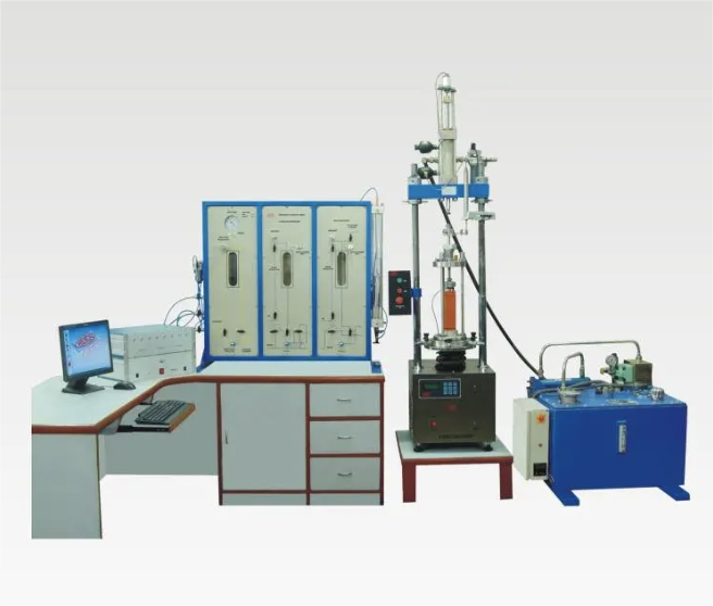
A triaxial test apparatus is a laboratory system used to apply controlled confining pressure and axial loading to a cylindrical soil specimen.
Depending on its configuration, the system can measure:
- Axial load
- Axial deformation
- Cell pressure
- Back pressure
- Pore-water pressure
- Drainage volume
- Specimen volume change
- Local strain
- Radial deformation
The apparatus may be configured for:
- UU—unconsolidated undrained testing
- CU—consolidated undrained testing
- CD—consolidated drained testing
- Stress-path testing
- Cyclic or repeated-load testing
- Unsaturated-soil testing
- Large-specimen testing
- Research applications
A complete apparatus is not simply a triaxial cell. It is an integrated system of mechanical loading, pressure control, drainage, measurement, specimen-mounting and data-acquisition components.
This guide explains the main components, how configurations differ and what laboratories should check when selecting or maintaining a triaxial test system.
Important: Equipment configuration, capacity, resolution, calibration and testing procedures must comply with the applicable ASTM, ISO, BS or other standard. This article does not replace the current test method or equipment manufacturer’s instructions.
What Does a Triaxial Test Apparatus Do?
A conventional soil triaxial apparatus creates an approximately axisymmetric stress condition.
The cell-pressure system applies radial confinement around the specimen. In a conventional test, the two radial principal stresses are normally equal:
[
\sigma_2 = \sigma_3
]
The loading frame increases the axial principal stress, (\sigma_1).
Deviator stress is commonly expressed as:
[
q = \sigma_1 – \sigma_3
]
For saturated soil, pore-water pressure may be measured so effective stress can be calculated:
[
\sigma’ = \sigma – u
]
where:
- (\sigma’) is effective stress;
- (\sigma) is total stress;
- (u) is pore-water pressure.
The apparatus must control or measure these quantities accurately enough for the selected test.
Main Components of a Triaxial Test Apparatus
| Component | Primary function |
|---|---|
| Loading frame | Applies controlled axial deformation or load |
| Triaxial cell | Contains the specimen and confining fluid |
| Cell-pressure controller | Applies and controls radial confinement |
| Back-pressure controller | Applies specimen back pressure |
| Pore-pressure transducer | Measures pore-water pressure |
| Volume-change device | Measures water entering or leaving the specimen |
| Load cell | Measures axial force |
| Displacement transducer | Measures axial deformation |
| Pedestal and top cap | Support and connect the specimen |
| Porous stones and filters | Distribute water and support drainage |
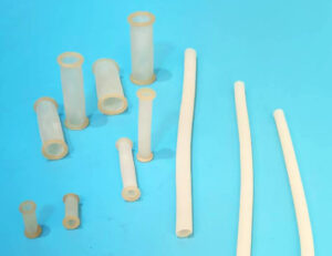
| Latex membrane | Separates specimen and cell fluid |
| Membrane stretcher | Assists membrane installation |
| O-rings | Seal membrane ends |
| Tubing and valves | Control pressure and drainage paths |
| Data-acquisition system | Records and processes measurements |
| De-aired water system | Supplies water with reduced dissolved or trapped air |
The required components depend on the test type.
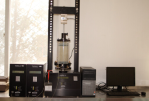
Figure 1. Replace this placeholder with an original photograph identifying the loading frame, cell, pressure controllers, transducers and data-acquisition system.
Axial Loading Frame
The loading frame applies axial compression to the specimen through the cell loading ram.
A suitable frame should provide:
- Adequate load capacity
- Stable low-speed movement
- Appropriate deformation-rate range
- Axial alignment
- Low vibration
- Sufficient vertical travel
- Compatibility with the triaxial cell
- Reliable speed control
- Emergency stop and overload protection
Strain-Controlled Loading
Many conventional triaxial compression methods use a controlled axial deformation rate.
The frame must maintain a sufficiently stable rate throughout the required travel.
Load-Controlled or Cyclic Loading
Specialized tests may require:
- Load control
- Stress control
- Repeated loading
- Sinusoidal loading
- Higher-frequency response
- Bidirectional loading
A standard static loading frame should not be assumed suitable for cyclic work.
Selecting Loading-Frame Capacity
Frame capacity should be based on:
- Specimen diameter
- Expected soil strength
- Maximum confining pressure
- Expected deviator stress
- Test type
- Required safety margin
- Cell and fixture weight
A larger specimen can generate significantly greater axial force at the same stress.
An oversized frame may provide the required capacity but still be unsuitable if it cannot maintain the low speeds or measurement resolution required for the test.
Triaxial Pressure Cell
The triaxial cell is a sealed chamber containing the specimen assembly and cell fluid.
Its main components may include:
- Cell base
- Transparent chamber wall
- Cell top
- Loading ram
- Pedestal
- Pressure inlet
- Drainage connections
- Internal tie rods
- Seals
- Safety enclosure
The cell must:
- Withstand the maximum intended pressure
- Provide sufficient internal clearance
- Match the specimen diameter
- Allow the required axial deformation
- Maintain pressure without unacceptable leakage
- Permit correct drainage connections
- Align with the loading frame
Cell Pressure Rating
Never operate a cell above its documented pressure rating.
The permitted operating pressure may also depend on:
- Chamber-wall material
- Cell condition
- Seal condition
- Loading-ram assembly
- Manufacturer instructions
- Safety regulations
- Inspection history
Pressure rating is a property of the complete cell assembly, not merely the chamber wall.
Specimen Size and Cell Selection
Common specimen diameters may include:
- 38 mm
- 50 mm
- 70 mm
- 100 mm
- 150 mm
- Larger custom sizes
The actual size must follow the applicable standard and particle-size requirements.
A cell selected for a particular specimen should provide:
- Correct pedestal diameter
- Correct top-cap diameter
- Adequate radial clearance
- Adequate vertical travel
- Suitable drainage connections
- Compatible membrane-stretcher access
- Sufficient pressure capacity
A large cell with a small pedestal is not automatically an appropriate small-specimen system.
Cell-Pressure Control System
The cell-pressure controller applies the confining pressure around the specimen.
Depending on the system, it may use:
- Manual regulators
- Pressure panels
- Air–water interfaces
- Screw-driven pressure/volume controllers
- Servo-controlled hydraulic systems
- Digital pressure controllers
Important characteristics include:
- Pressure range
- Resolution
- Accuracy
- Stability
- Volume capacity
- Response time
- Control mode
- Calibration
- Overpressure protection
- Compatibility with the cell fluid
A high maximum-pressure rating does not guarantee good low-pressure control. Low-pressure tests may require a controller with suitable resolution and stability near the bottom of its range.
Back-Pressure Control System
Back pressure is used in saturated CU and CD testing as part of specimen saturation and pressure control.
A back-pressure system may include:
- Pressure/volume controller
- Reservoir
- De-aired water
- Tubing
- Valves
- Pedestal and top-cap connections
- Volume measurement
The system should provide:
- Stable pressure
- Suitable volume capacity
- Low leakage
- Low compliance
- Adequate resolution
- Reliable connection to the specimen drainage paths
Not every triaxial test uses back pressure. A standard UU configuration does not use the same separate saturation and back-pressure process as CU or CD testing.
Pore-Pressure Measurement
A pore-pressure transducer measures water pressure within the specimen drainage system.
It is especially important for CU tests because effective stresses are calculated using measured pore pressure.
Selection considerations include:
- Pressure range
- Resolution
- Accuracy
- Overpressure tolerance
- Temperature sensitivity
- Zero stability
- Calibration
- Fluid compatibility
- Internal volume
The measurement line should be:
- Properly saturated
- Free of trapped air
- As short as practical
- Protected from leakage
- Connected to the correct specimen boundary
Trapped air increases system compliance and can delay or distort pore-pressure response.
Volume-Change Measurement
Volume-change measurement is used during:
- Saturation
- Consolidation
- Drained shearing
- Permeability-related procedures
- Specialized stress paths
Devices may include:
- Pressure/volume controllers
- Burettes
- Differential pressure systems
- Digital volume-change units
- Cell-volume measurement systems
The measurement may be affected by:
- Tubing compliance
- Fluid compressibility
- Temperature changes
- Leakage
- Controller deformation
- Membrane penetration
- Evaporation in open systems
- Incorrect zeroing
The laboratory must distinguish specimen volume change from apparatus response.
Load Cell
The load cell measures axial force.
It may be installed:
- Outside the triaxial cell
- Inside the cell
- In another manufacturer-defined position
External Load Cell
Possible benefits:
- Easier installation
- Easier calibration
- Protection from cell fluid
Possible limitations:
- Loading-ram friction may be included in the measurement.
- Cell-seal friction can influence low-load results.
- Alignment effects may be more significant.
Internal Load Cell
Possible benefits:
- Measures force closer to the specimen
- Can reduce loading-ram friction effects
Possible limitations:
- Must withstand cell pressure and fluid exposure
- More difficult servicing
- Requires appropriate pressure compensation and calibration
The choice depends on required accuracy, pressure range and apparatus design.
Selecting Load-Cell Capacity
The load cell should:
- Exceed the maximum expected force
- Provide adequate resolution at expected working loads
- Remain within its calibrated range
- Avoid unnecessary oversizing
- Have suitable overload protection
A very large-capacity load cell may be too insensitive for a small, weak specimen.
Axial Deformation Measurement
Axial deformation may be measured using:
- LVDT
- Displacement transducer
- Dial gauge
- Frame encoder
- Internal displacement sensor
The sensor should have:
- Adequate travel
- Suitable resolution
- Stable mounting
- Correct alignment
- Current calibration
- Protection from overtravel
External axial deformation includes deformation in the loading system and contact seating unless corrected.
Local Strain Measurement
Advanced systems may measure local axial or radial strain directly on or near the specimen.
Possible benefits include:
- Better small-strain resolution
- Reduced influence from frame compliance
- Measurement before major localization
- More accurate stiffness determination
Local instrumentation adds complexity and may affect the specimen or membrane boundary.
It requires:
- Suitable mounting
- Calibration
- Data synchronization
- Protection during cell assembly
- A validated interpretation method
Data-Acquisition System
The data-acquisition system records signals from:
- Load cells
- Displacement sensors
- Pressure transducers
- Volume controllers
- Local strain sensors
- Temperature sensors
Important requirements include:
- Correct channel configuration
- Appropriate sampling rate
- Sensor excitation compatibility
- Unit conversion
- Calibration factors
- Time synchronization
- Raw-data storage
- Backup
- Audit trail
- Export capability
Automated calculations should be checked independently.
Common setup errors include:
- Wrong specimen dimensions
- Incorrect sensor range
- Incorrect unit conversion
- Reversed sign convention
- Old calibration factor
- Incorrect zero
- Wrong channel assignment
- Incorrect area correction
Raw sensor data should be retained separately from processed results.
Specimen Pedestal and Top Cap
The pedestal and top cap support the specimen and provide drainage or pore-pressure connections.
They should:
- Match the specimen diameter
- Be aligned
- Have smooth sealing surfaces
- Be free from sharp edges
- Hold porous stones correctly
- Connect securely to tubing
- Support reliable O-ring sealing
A mismatch between specimen, pedestal and top cap can cause:
- Membrane folds
- End leakage
- Stress concentrations
- Misalignment
- Specimen damage
- Nonuniform deformation
Porous Stones and Filter Materials
Porous stones distribute water across the specimen ends and provide drainage connections.
They should be:
- Clean
- Flat
- Compatible with specimen diameter
- Sufficiently permeable
- Free from blocked pores
- Properly saturated when required
- Stored and handled according to laboratory procedures
Filter paper may be used where permitted to:
- Prevent soil intrusion into porous stones
- Assist drainage
- Provide side drains in selected procedures
Filter materials can affect specimen dimensions, drainage and corrections and should be reported where required.
Latex Membrane
The latex membrane separates the soil specimen from the cell fluid.
It must have:
- Suitable material
- Correct inside diameter
- Sufficient length
- Appropriate wall thickness
- Reliable elasticity
- Acceptable dimensional uniformity
- No visible pinholes, cuts or cracks
The membrane should fit the specimen and end components without excessive looseness or damaging stretch.
Potential membrane-related errors include:
- Leakage
- Puncture
- Wrinkles
- End-seal failure
- Membrane restraint
- Membrane penetration
- Local wall thinning
Membrane Stretcher
A membrane stretcher expands the membrane before it is lowered over the specimen.
It should:
- Match the specimen size
- Match the membrane size
- Have smooth edges
- Maintain vacuum
- Release the membrane evenly
- Be clean and undamaged
Dragging an unstretched membrane directly over a fragile specimen can disturb the soil and damage the membrane.
O-Rings and End Seals
O-rings secure the membrane around the pedestal and top cap.
Check:
- Inside diameter
- Cross-section
- Material condition
- Surface damage
- Groove position
- Installation method
- Membrane overlap
- Number of seals required
An excessively tight or damaged O-ring can cut the membrane. An undersized sealing area can allow it to slip during deformation.
Pressure and Drainage Circuit
A complete system may include separate paths for:
- Cell pressure
- Bottom drainage
- Top drainage
- Back pressure
- Pore-pressure measurement
- Volume-change measurement
- De-airing
- Flushing
Each valve should be:
- Clearly identified
- Leak-free
- Operated in the correct sequence
- Compatible with the pressure range
- Documented in a circuit diagram
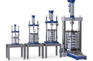
Figure 2. Replace this placeholder with an original schematic showing cell pressure, back pressure, pore pressure and drainage lines.
UU Apparatus Configuration
A UU system typically requires:
- Loading frame
- Triaxial cell
- Cell-pressure controller
- Load measurement
- Axial displacement measurement
- Pedestal and top cap
- Membrane and O-rings
- Data acquisition
A standard UU test does not use the same saturation, consolidation and pore-pressure-measurement stages as a CU test.
CU Apparatus Configuration
A CU system typically requires:
- Loading frame
- Triaxial cell
- Cell-pressure controller
- Back-pressure controller
- Pore-pressure transducer
- Volume-change measurement
- Drainage valves
- De-aired water system
- Load measurement
- Deformation measurement
- Data acquisition
- Membrane and sealing components
The system must support:
- Saturation
- Saturation verification
- Consolidation
- Undrained shearing
- Pore-pressure measurement
- Effective-stress calculation
CD Apparatus Configuration
A CD system requires:
- Saturation capability
- Consolidation control
- Stable cell and back pressures
- Drainage during shearing
- Accurate volume-change measurement
- Very stable low loading rates
- Long-duration system integrity
Because drainage must be maintained, the system’s loading-rate control and volume measurement are especially important.
Slow leakage can be mistaken for specimen volume change.
Apparatus Requirements by Test Type
| Capability | UU | CU | CD |
|---|---|---|---|
| Controlled cell pressure | Required | Required | Required |
| Axial load measurement | Required | Required | Required |
| Axial deformation measurement | Required | Required | Required |
| Back pressure | Normally not part of standard setup | Required | Required |
| Pore-pressure measurement | Not normally primary | Required | May be used for condition verification |
| Consolidation volume | No separate consolidation stage | Required | Required |
| Drainage during shear | Closed | Closed | Open |
| Volume change during shear | Not measured as drained volume | No drainage | Required |
| Long-duration stability | Moderate | High | Often very high |
Equipment Selection Checklist
Test Requirements
Confirm:
- Test types
- Applicable standards
- Soil types
- Maximum particle size
- Specimen diameters
- Maximum cell pressure
- Maximum back pressure
- Maximum axial load
- Deformation-rate range
- Expected test duration
- Required measurements
Triaxial Cell
Confirm:
- Pressure rating
- Specimen compatibility
- Internal clearance
- Vertical travel
- Pedestal options
- Drainage ports
- Seal availability
- Safety features
Loading Frame
Confirm:
- Load capacity
- Speed range
- Speed stability
- Travel
- Control mode
- Cell clearance
- Overload protection
Pressure Controllers
Confirm:
- Pressure range
- Resolution
- Accuracy
- Stability
- Volume capacity
- Response time
- Control mode
- Calibration procedure
Sensors
Confirm:
- Measurement range
- Resolution
- Accuracy
- Overload tolerance
- Temperature sensitivity
- Calibration
- Data-system compatibility
Consumables
Confirm availability of:
- Latex membranes
- O-rings
- Porous stones
- Filter paper
- Tubing
- Fittings
- Seals
- De-aired water
- Replacement cell parts
An apparatus may become difficult to operate if essential consumables or seals are proprietary and unavailable.
Avoid Selecting Equipment by Maximum Capacity Alone
A system advertised with very high load or pressure capacity may still be unsuitable for weak soils.
For low-stress tests, the system also needs:
- Low-range measurement resolution
- Stable low pressure
- Low loading speed
- Low friction
- Low leakage
- Appropriate load-cell range
Laboratories testing both soft clay and strong compacted material may need:
- Interchangeable load cells
- Multiple pressure ranges
- Different triaxial cells
- Multiple pedestal sizes
- Configurable sensors
Calibration and Verification
A maintenance program should address:
- Load cell
- Axial displacement sensor
- Pressure transducers
- Pressure controllers
- Volume-change devices
- Frame speed
- Data-acquisition channels
- Temperature sensors
- Local strain devices
Additional checks may include:
- Cell leakage
- Tubing leakage
- Valve leakage
- Loading-ram friction
- System compliance
- Volume-controller response
- Drainage-system saturation
- Zero stability
Calibration frequency should follow the laboratory quality system, standard and equipment manufacturer’s requirements.
System Compliance
The pressure and volume system is not perfectly rigid.
Measured volume may include:
- Tubing expansion
- Fluid compression
- Controller deformation
- Cell deformation
- Sensor response
- Temperature effects
- Membrane penetration
A rigid dummy specimen may help characterize part of the apparatus response, but it does not reproduce the surface voids of a granular soil specimen.
System corrections should be:
- Validated
- Documented
- Appropriate to the pressure range
- Rechecked after system modifications
Loading-Ram Friction
Ram seals can introduce friction into axial-force measurement, especially when the load cell is external to the cell.
The possible influence depends on:
- Seal design
- Cell pressure
- Ram condition
- Alignment
- Lubrication permitted by the manufacturer
- Loading direction
- Measurement arrangement
If relevant, determine and apply the correction required by the apparatus procedure.
An internal load cell may reduce some ram-friction effects but introduces other pressure, fluid and calibration considerations.
Leakage Testing
Possible leak locations include:
- Cell chamber
- Cell base
- Loading-ram seal
- Tubing
- Fittings
- Valves
- Controllers
- Drainage connections
- Membrane
- O-rings
A practical sequence is:
- Test the controller and tubing.
- Isolate the cell.
- Test the empty cell assembly.
- Check the loading-ram seal.
- Check drainage connections.
- Inspect the membrane and O-rings.
- Record the pressure, time and temperature.
- Correct the source before preparing another specimen.
Do not automatically blame the latex membrane for every pressure loss.
Common Equipment Problems
| Problem | Possible cause | Recommended check |
|---|---|---|
| Cell pressure falls | Cell, valve, fitting or membrane leak | Isolate the pressure circuit |
| Back pressure is unstable | Air, controller problem or leakage | De-air and inspect the circuit |
| Pore pressure responds slowly | Trapped air or excessive dead volume | Check saturation of measurement lines |
| Volume changes during a hold | Temperature, leakage or compliance | Run a system baseline |
| Axial load is unusually high | Friction, misalignment or incorrect area correction | Check ram, frame and calculations |
| Load signal is noisy | Electrical noise, vibration or loose connection | Check wiring and grounding |
| Displacement does not change | Sensor slip or end of travel | Inspect sensor mounting |
| Specimen tilts | Uneven ends or poor alignment | Check preparation and centering |
| Membrane tears repeatedly | Sharp component or incorrect fit | Inspect stretcher, pedestal and top cap |
| Software result is incorrect | Wrong units or calibration factor | Check raw signals and configuration |
Data Quality Checks Before Testing
Before starting:
- Verify the correct specimen dimensions.
- Confirm sensor identification.
- Check calibration factors.
- Confirm units.
- Check sign conventions.
- Zero sensors according to procedure.
- Verify valve positions.
- Confirm pressure limits.
- Check available controller volume.
- Confirm data-storage location.
- Start raw-data recording.
- Verify that all live readings are plausible.
A single incorrect diameter can affect calculated area, stress and strain throughout the test.
Maintenance
Routine maintenance may include:
- Cleaning the cell
- Inspecting chamber walls
- Replacing seals
- Inspecting the loading ram
- Checking tubing
- Tightening fittings
- Cleaning porous stones
- Verifying valves
- Checking controller fluid
- Inspecting electrical connections
- Updating calibration records
- Replacing damaged O-rings
- Inspecting membrane stretchers
Maintenance materials must be compatible with the equipment and test fluids.
What Information Should Be Included in an Equipment Specification?
When requesting a triaxial apparatus quotation, provide:
- Required test types
- Applicable standards
- Soil types
- Specimen diameters
- Maximum particle size
- Maximum cell pressure
- Maximum back pressure
- Expected axial load
- Required deformation rate
- Test duration
- Required measurements
- Number of simultaneous stations
- Automation requirements
- Power supply
- Data-export format
- Calibration requirements
- Training requirements
- Spare parts
- Warranty and service location
- Consumable requirements
Do not request only “one complete triaxial machine.” Different test programs require materially different configurations.
Frequently Asked Questions
Is a triaxial cell the same as a triaxial apparatus?
No.
The cell is the pressure chamber containing the specimen. The apparatus includes the cell, loading frame, pressure controllers, sensors, drainage system, data acquisition and specimen-mounting components.
Can one apparatus perform UU, CU and CD tests?
Many modular systems can, provided they include the required pressure, drainage, pore-pressure and volume-change capabilities.
A basic UU system may not have everything needed for CU or CD testing.
Does every apparatus need a pore-pressure transducer?
Pore-pressure measurement is essential for effective-stress interpretation in CU testing. It is not normally a primary output of a standard UU test.
Does every apparatus need back pressure?
No. Back-pressure capability is required for saturation procedures used in CU and CD testing but is not part of the same standard UU procedure.
What pressure capacity should I choose?
Choose capacity according to the applicable test program, expected stresses and safety requirements.
Also check low-pressure resolution and stability. Maximum pressure alone is not enough.
What load-cell capacity should I choose?
Estimate the maximum expected axial force from specimen area and stress, then choose an appropriate calibrated range and safety margin.
Avoid a greatly oversized sensor if low-load resolution is important.
Why is de-aired water used?
Trapped or dissolved air can increase compliance and interfere with saturation, pressure and volume measurements.
The required water preparation must follow the applicable procedure.
Why is a latex membrane required?
It separates the specimen from cell fluid and maintains the intended drainage boundary while allowing confining pressure to act around the specimen.
Can a membrane change the result?
Yes. Membrane restraint and membrane penetration can affect measurements. Leakage or poor installation can invalidate the test.
How often should the apparatus be calibrated?
Follow the laboratory quality system, applicable standard, equipment manufacturer and accreditation requirements. Recalibration or verification may also be needed after repair, overload or relocation.
Conclusion
A triaxial test apparatus is an integrated loading, pressure-control, drainage and measurement system.
A reliable configuration requires matching:
- Test type
- Specimen size
- Soil strength
- Pressure range
- Load range
- Deformation rate
- Sensor resolution
- Drainage requirements
- Test duration
- Membrane dimensions
- Data-acquisition capability
UU, CU and CD tests require different levels of pressure control, saturation, drainage and measurement.
Equipment should not be selected solely by maximum load, maximum pressure or price. Resolution, stability, leakage, compliance, calibration, consumables and after-sales support are equally important.
Discuss Your Triaxial Membrane Requirements
If you need a membrane for an existing triaxial apparatus, provide:
- Specimen diameter
- Specimen height
- Pedestal diameter
- Top-cap diameter
- Required membrane length
- Preferred thickness
- Cell-pressure range
- Expected strain
- Test type
- Equipment model
- Required quantity
We can review standard tubular membranes and custom dimensional requirements.
[Button: Discuss Your Triaxial Membrane Requirements]
Technical References
- ASTM International. ASTM D2850—Unconsolidated-Undrained Triaxial Compression Test on Cohesive Soils.
- ASTM International. ASTM D4767—Consolidated Undrained Triaxial Compression Test for Cohesive Soils.
- ASTM International. ASTM D7181—Consolidated Drained Triaxial Compression Test for Soils.